Electromagnetic Interference Noise Separator

a technology of electromagnetic interference and separator, which is applied in the direction of line-transmission, current interference reduction, line-transmission details, etc., can solve the problems of generating electromagnetic interference (emi) noise at the input of the power source, emi noise may also be generated, and emi noise has detrimental effects on the operation of electrical and electronic products

Inactive Publication Date: 2011-03-03
VIRGINIA TECH INTPROP INC
View PDF2 Cites 20 Cited by
  • Summary
  • Abstract
  • Description
  • Claims
  • Application Information

AI Technical Summary

Benefits of technology

[0005]It is therefore an object of the present invention to provide a noise separator circuit which can accurately se

Problems solved by technology

However, to achieve high efficiency of such power conversion, power supplies employ switching circuits which control frequency and/or duty cycle of current pulses drawn from a power source to achieve the desired voltage with good regulation and thus inherently generate electromagnetic interference (EMI) noise at the input from the power source.
EMI noise may also be generated by fluctuations in the amount on power drawn by the electrical or electronic device such as the large current swings that may be produced by a data processing or logic array circuit as switching is performed in a highly parallel and clocked fashion between periods in a stand-by state during which comparatively little power is drawn.
Conducted EMI noise has detrimental effects on operation of electrical and electronic products, particularly due to the high frequencies present therein which can cause heating in batteries or cause fluctuations in power deliv

Method used


Image

  • Electromagnetic Interference Noise Separator
  • Electromagnetic Interference Noise Separator
  • Electromagnetic Interference Noise Separator

Examples


Embodiment Construction

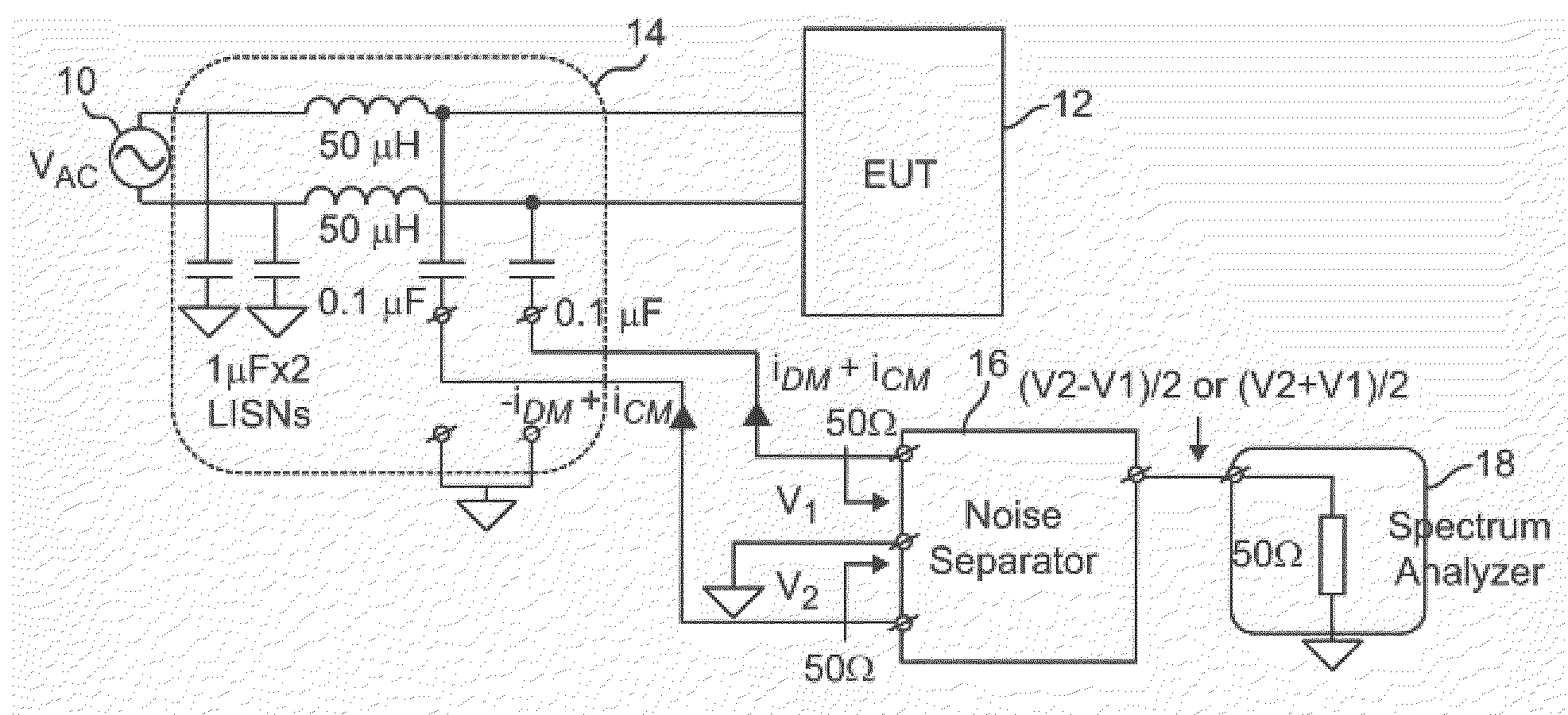
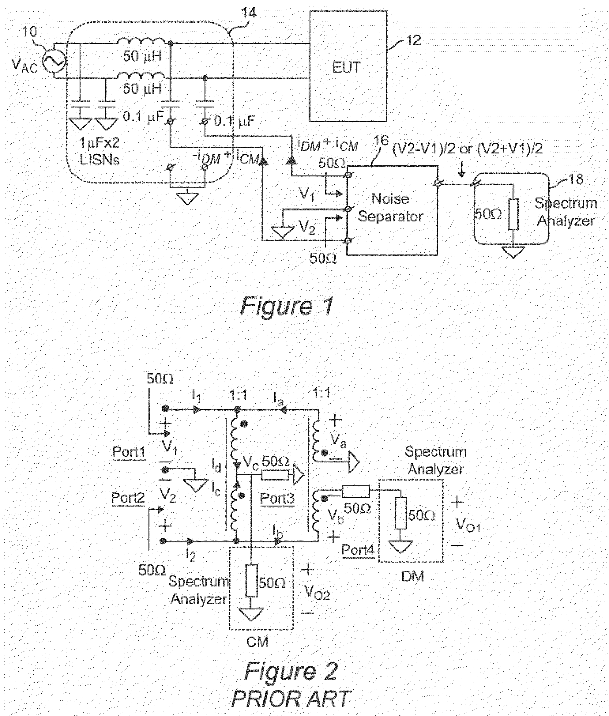
[0021]Referring now to the drawings, and more particularly to FIG. 1, there is shown a generalized test arrangement for measurement of CM or DM noise to which the invention is applicable. Since FIG. 1 is arranged to facilitate an understanding of the nature of the problem addressed by the invention and depicts inclusion of an ideal noise separator circuit which the invention closely approaches by virtue of being symmetrical and embodied using particular design techniques as will be discussed below in connection with FIGS. 11-18, no portion of FIG. 1 is admitted to be prior art in regard to the present invention.

[0022]FIG. 1 shows a generalized power source 10 as, for purposes of discussion, an alternating current (AC) power source since conducted EMI noise is principally regulated to limit noise levels coupled to a power distribution grid. However, it is to be understood that the power source could be a battery or other source delivering power as direct current (DC) at a nominally c...


PUM


Abstract

Improved performance of a noise separator circuit capable of separating common mode (CM) and differential mode (DM) components of electromagnetic interference (EMI) noise are provided by arrangement of terminating impedances such that the circuit is fully symmetric with respect of a pair of input ports. The noise separator circuit is further improved by perfecting features for canceling effects of parasitic inductances and capacitances, parasitic capacitance and inductance between circuit connections such as printed circuit board traces, minimizing leakage inductance effects of pairs of coupled inductors and mutual inductance effects between pairs of coupled inductors, providing sufficient magnetizing inductance for low frequency response, and preventing saturation of inductors using switched attenuators, providing a plurality of ground planes, choices of terminating resistors and circuit layout.

Description

FIELD OF THE INVENTION[0001]The present invention generally relates to measurement of common mode (CM) and differential mode (DM) noise components present in conducted electromagnetic interference (EMI) noise which may be presented at the power input to an electrical or electronic device and, more particularly, to a device for accurately separating CM and DM noise components over a wide frequency band for conducted EMI diagnosis and power transformer and filter circuit design.BACKGROUND OF THE INVENTION[0002]Many electrical and electronic devices are designed and constructed to operate from power at a substantially constant voltage and include a power supply to convert power from an alternating current or battery input to the required nominal voltage. However, to achieve high efficiency of such power conversion, power supplies employ switching circuits which control frequency and / or duty cycle of current pulses drawn from a power source to achieve the desired voltage with good regul...

Claims


Application Information

Patent Timeline
IPC IPC(8): H03H7/38
CPCH03H1/0007H03H2001/0057H03H7/0115
Inventor WANG, SHUOLEE, FRED C.
Owner VIRGINIA TECH INTPROP INC
Why Eureka
Try Eureka