Reflective optical element for use in an EUV system

Active Publication Date: 2011-03-03
CARL ZEISS SMT GMBH
View PDF8 Cites 27 Cited by
  • Summary
  • Abstract
  • Description
  • Claims
  • Application Information

AI Technical Summary

Benefits of technology

[0024]In certain embodiments, a reflection layer is applied to the polishing layer in a subsequent step. The p

Problems solved by technology

However, these substrate materials are often suitable only to a limited extent for operation with very high thermal loads which can occur at high radiation powers.
In these cases, a thermal conductivity of the known mirror materials is often too low to conduct away enough heat from the reflective

Method used


Image

  • Reflective optical element for use in an EUV system
  • Reflective optical element for use in an EUV system
  • Reflective optical element for use in an EUV system

Examples


Embodiment Construction

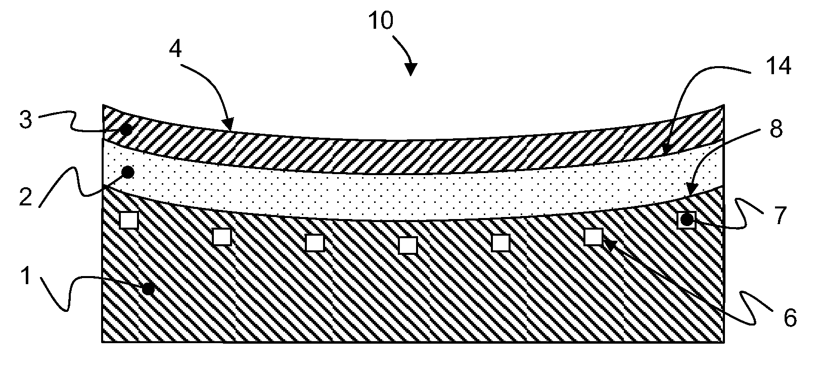
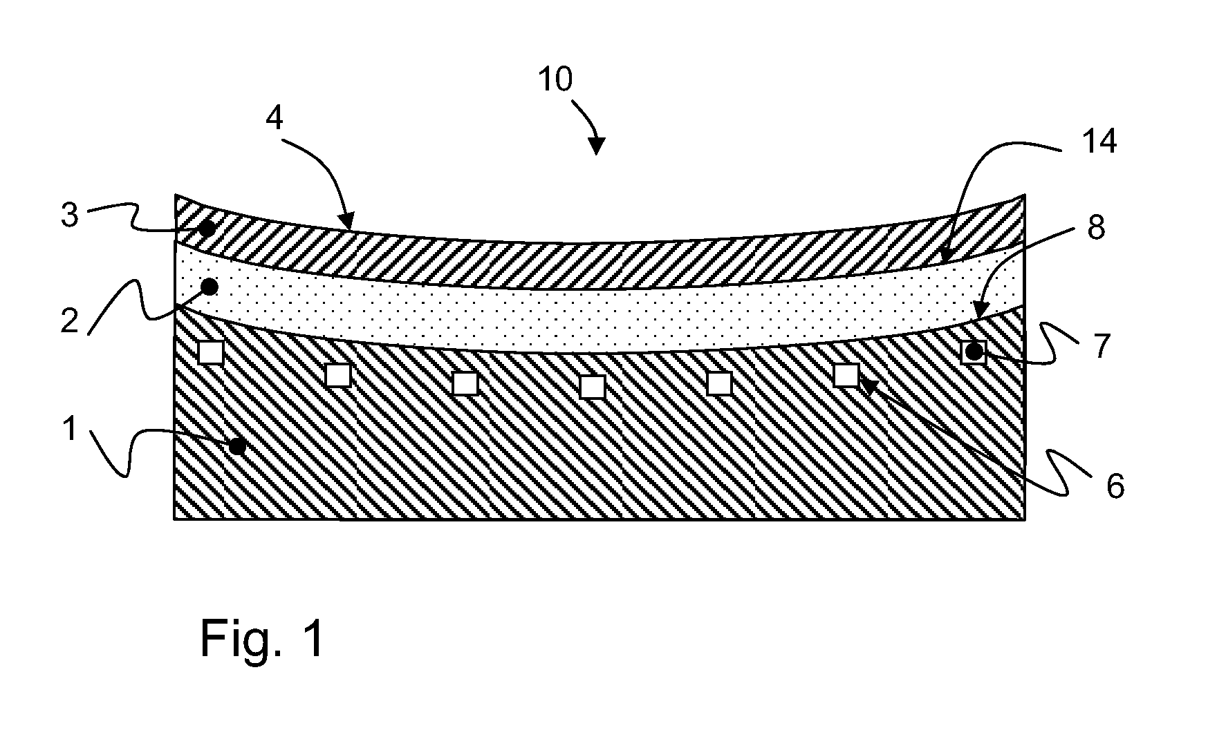
[0028]FIG. 1 illustrates an optical element according to the disclosure in the form of a collector mirror 10, which is provided for optical applications in an extreme ultraviolet (EUV) wavelength range of 10 nm to 15 nm, in particular of 13.5 nm. The collector mirror 10 includes a base body 1, a polishing layer 2, a reflection layer 3 and cooling channels 6.

[0029]In a first exemplary embodiment, the base body 1 is produced from a ceramic substrate, in particular from silicon carbide SiC or from silicon-infiltrated silicon carbide SiSiC. These materials are distinguished by a good thermal conductivity of 120 to 170 W / mK, a high stiffness, characterized by a modulus of elasticity of 250-350 GPa, and also a very low coefficient of thermal expansion of approximately 3 ppm / K and a low density of approximately 3 g / cm3.

[0030]In a second exemplary embodiment, the base body 1 is produced from a metal composite substrate, in particular from silicon carbide dispersion strengthened aluminum AlS...


PUM


Abstract

A reflective optical element (10) for use in an EUV system is disclosed. The reflective optical element includes a base body, which is produced at least partly from a substrate material. At least one cooling channel through which a cooling medium can flow is arranged in the base body. A material having a thermal conductivity of greater than 50 W/mK is provided as substrate material. The reflective optical element also includes a polishing layer, which is applied on the substrate material. The polishing layer includes an amorphous material which can be processed via polishing.

Description

CROSS-REFERENCE TO RELATED APPLICATIONS[0001]This application claims priority under 35 U.S.C. §119(e)(1) to U.S. Provisional Application No. 61 / 238,364 filed Aug. 31, 2009. This applications also claims priority under 35 U.S.C. §119 to German Patent Application DE 10 2009 039 400.1, filed Aug. 31, 2009. The contents of both of these applications are hereby incorporated by reference in its entirety.FIELD[0002]The disclosure relates to a reflective optical element for use in an EUV lithography system including a base body, which is produced at least partly from a substrate material. At least one cooling channel through which a cooling medium can flow is arranged in the base body.BACKGROUND[0003]For optical applications in the extreme ultraviolet wavelength range (EUV) particularly in lithography, almost exclusively reflective optical elements are usually used, the surfaces of which desirably satisfy stringent desired properties with regard to figure and roughness. It is known from to ...

Claims


Application Information

Patent Timeline
IPC IPC(8): G02B5/08
CPCG02B5/0891G02B7/1815G02B7/181G03F7/70891G03F7/7095G03F7/70316
Inventor KIEREY, HOLGERLE MAIRE, MICHELANDERL, WILLIHOLDERER, HUBERTLENGEL, ANTON
Owner CARL ZEISS SMT GMBH
Why Eureka
Try Eureka