Method of driving a well pump

a well pump and well pump technology, applied in the direction of pumps, mechanical equipment, fluid removal, etc., can solve the problems of high capital cost of pump jack, rod string and insert pump, and the inability to maintain the pumping system

Inactive Publication Date: 2011-03-03
WELLS ROBERT MICHAEL
View PDF8 Cites 7 Cited by
  • Summary
  • Abstract
  • Description
  • Claims
  • Application Information

AI Technical Summary

Benefits of technology

[0064]7. Due to the utilization of differential areas and force multiplication within the pump a low

Problems solved by technology

The disadvantages of an insert pumping system are widely acknowledged in the oil and gas industry.
Up front capital costs to install a pump jack, rod string and insert pump are significant and require the use of a workover rig.
Day rates and availability of workover rigs in periods of high activity warrant sp

Method used


Image

  • Method of driving a well pump
  • Method of driving a well pump
  • Method of driving a well pump

Examples


Embodiment Construction

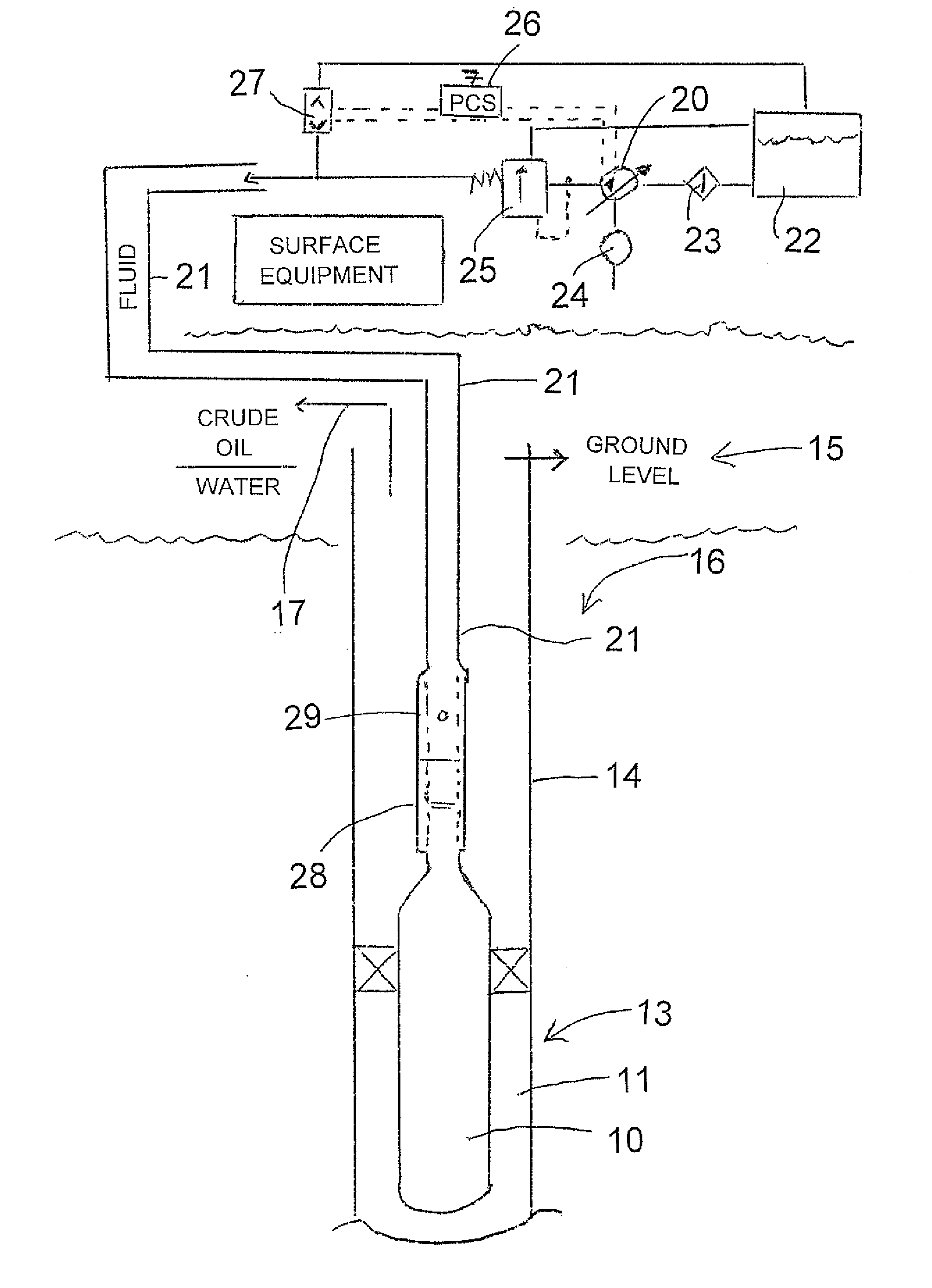
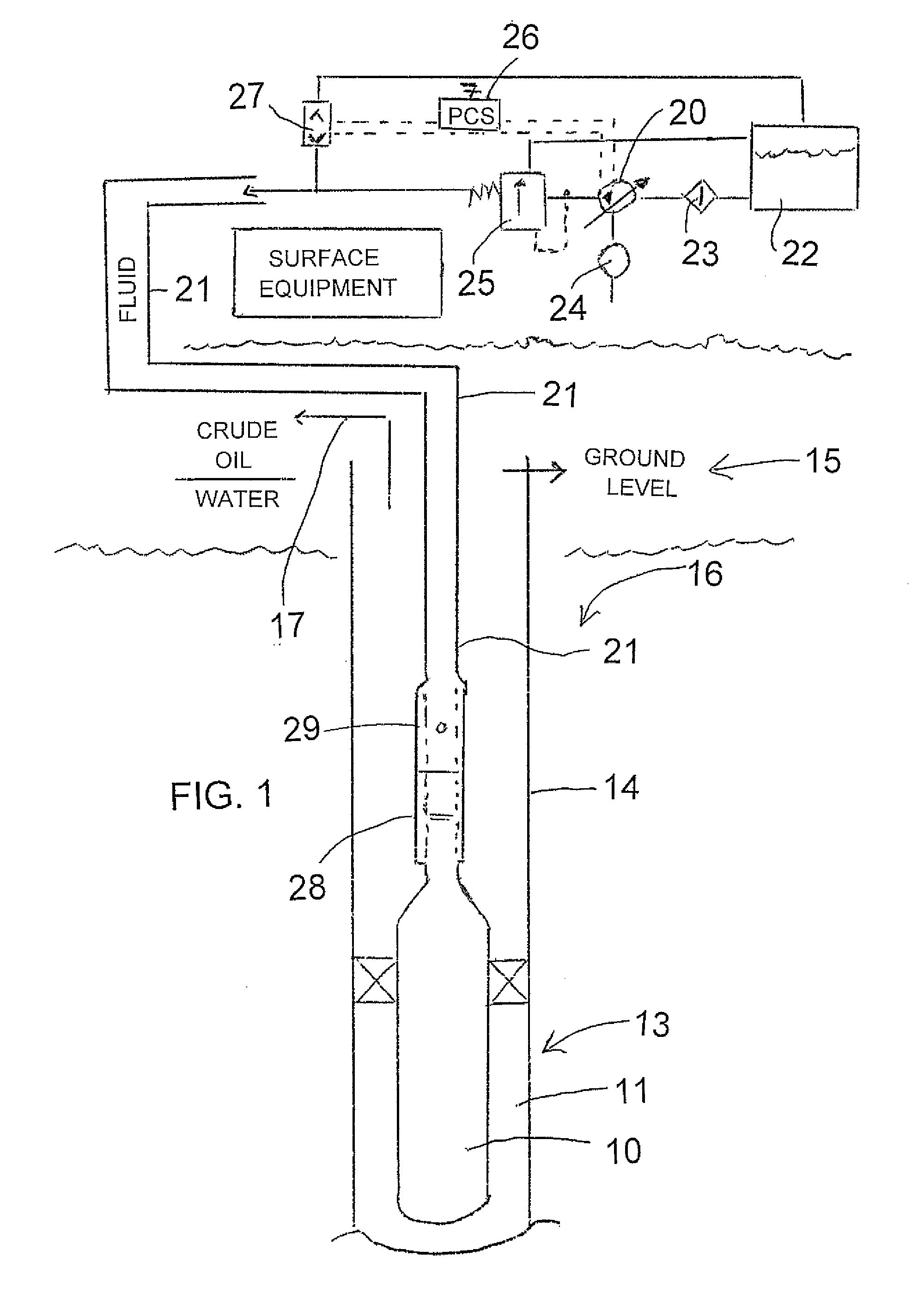
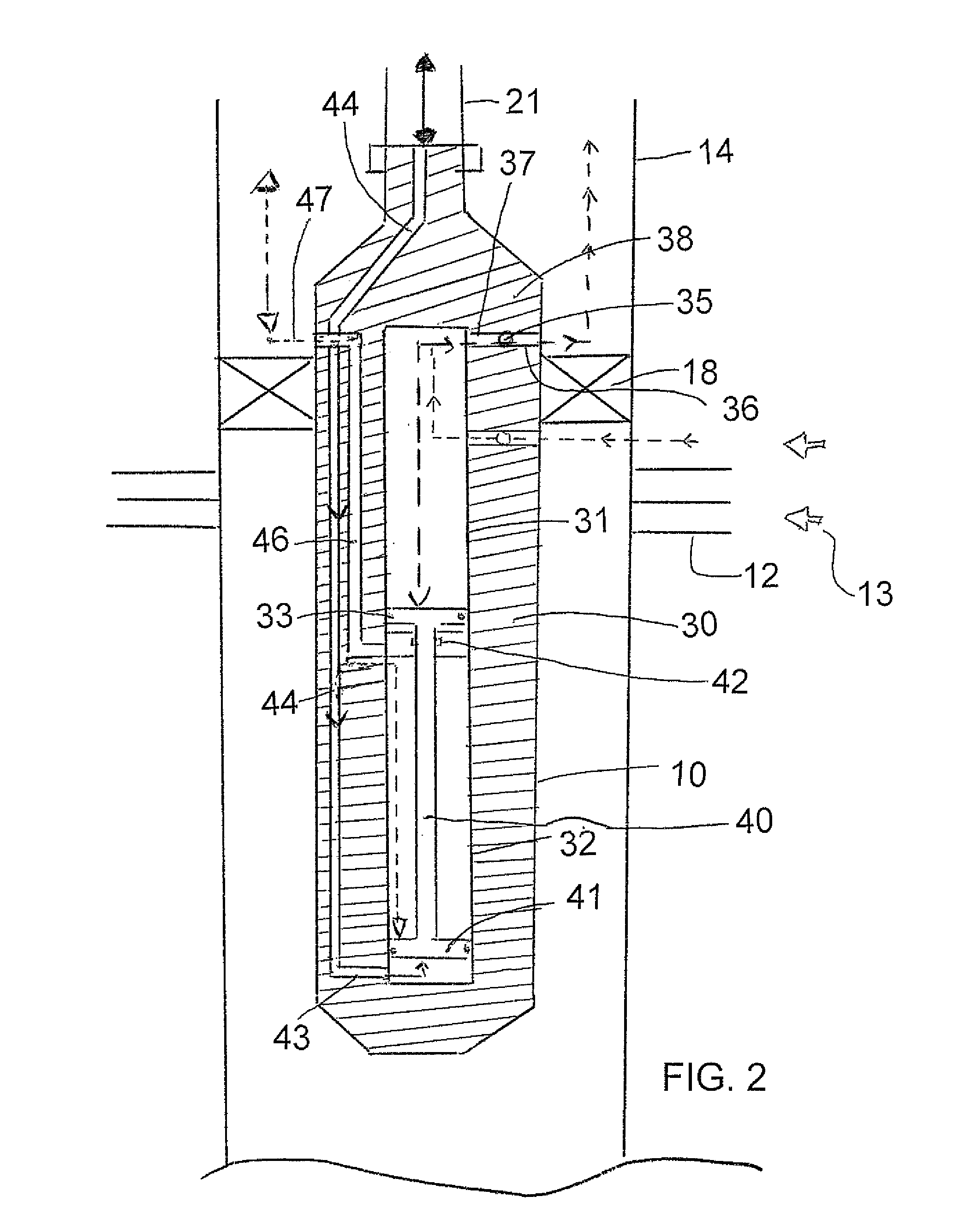
[0070]The system illustrated comprises a down hole reciprocating piston pump 10 which is mounted in a well bore 11 at a production location 12 where production liquid 13 enters into the pump 10 for pumping to the surface through a well casing 14. At the surface 15 above the ground 16 is provided a liquid recovery system 17 of a conventional nature for receiving the pumped liquid for transportation or storage as required using conventional systems.

[0071]The pump is mounted within the well casing 14 by a packing system 18 which locates the pump within the well casing and also divides well casing into a production zone below the packing and into a transportation zone above the packing. Thus, as is conventional in such pumps, the liquid is transferred by the pump from the location below the packing into the well casing so that the production liquid is carried up the well casing by the addition of further liquid into the well casing by the pumping action.

[0072]In the surface equipment as...


PUM


Abstract

Production liquid from a well is pumped to the surface by a hydraulically driven reciprocating piston pump. The pump is driven in a drive stroke by a flow of hydraulic fluid supplied through a single tubing line applied to a drive side of a drive piston and in a return stroke by the weight of the production liquid heavier than the hydraulic fluid applied to the return side of the drive piston. The production liquid is pumped though the well casing. A control valve causes application of pressure in the hydraulic fluid for the drive stroke and release for the return stroke. The pump body includes a first duct communicating between the tubing and the bottom drive side of the drive piston and a second duct communicating between the well casing and the top drive return of the drive piston.

Description

[0001]This invention relates to a method of driving a well pump.BACKGROUND OF THE INVENTION[0002]Down-hole hydraulic pumps with the valving, piston and pump (and its variations) were originally developed under the trade names “Kobe” and “Oilmaster”. Both have been available to the industry for more than five decades. The product enjoys worldwide acceptance under the current direction of Weatherford Oil Tool. These pumps find special application lifting large volumes of light oil in deep wells.[0003]More recently Canadian application 2,258,237 by Cunningham suggested bringing the valving to the surface, and proposed using a downhole double acting hydraulic piston, three (3) strings of tube and a conventional oil well pump for placement in a horizontally drilled heavy oil well. The double acting feature of the hydraulic piston would be particularly useful as a pump pull-down in the highly viscous heavy oil applications for which the system was conceived.[0004]Canadian application 2,26...

Claims


Application Information

Patent Timeline
IPC IPC(8): F04B47/00F04B7/04E21B43/00
CPCE21B43/129F04B47/08F04B47/04
Inventor WELLS, ROBERT MICHAEL
Owner WELLS ROBERT MICHAEL
Why Eureka
Try Eureka