
Advanced memory device having improved performance, reduced power and increased reliability

a memory device and advanced technology, applied in the field of memory devices, can solve problems such as exacerbate the design challenges of computer systems

Active Publication Date: 2011-03-03
GLOBALFOUNDRIES US INC
View PDF12 Cites 148 Cited by
  • Summary
  • Abstract
  • Description
  • Claims
  • Application Information

AI Technical Summary

Benefits of technology

The present invention is related to a memory device with various features and advantages. One feature is the inclusion of error control coding circuitry for checking the received command for errors and data masking circuitry for preventing data from being written to the memory array if an error is detected. Another feature is the use of an internal clock for generating clock signals and a data strobe driver for generating a data strobe signal to capture data on a data bus. The programmable preamble control circuitry is used to determine when the data strobe preamble is completed and initiate the refresh of one or more memory cells on the memory array. The memory device also includes self-refresh circuitry for operating the memory device in a self-refresh mode and programmable circuits for determining when the refresh command should be performed based on the characteristic of the memory device. Overall, the present invention provides improved error checking, data masking, and self-refresh capabilities for memory devices.

Problems solved by technology

High-availability systems present further challenges as related to overall system reliability due to customer expectations that new computer systems will markedly surpass existing systems in regard to mean-time-between-failure (MTBF), in addition to offering additional functionality, increased performance, increased storage, lower operating costs, etc.
Other frequent customer requirements further exacerbate the computer system design challenges, and include such items as ease of upgrade and reduced system environmental impact (such as space, power, and cooling).

Method used


Image

  • Advanced memory device having improved performance, reduced power and increased reliability
  • Advanced memory device having improved performance, reduced power and increased reliability
  • Advanced memory device having improved performance, reduced power and increased reliability

Examples


Embodiment Construction

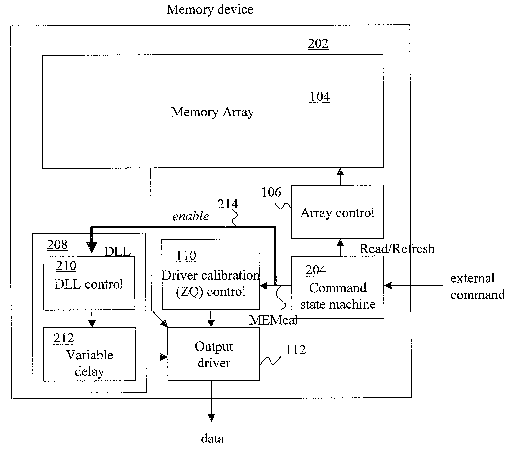
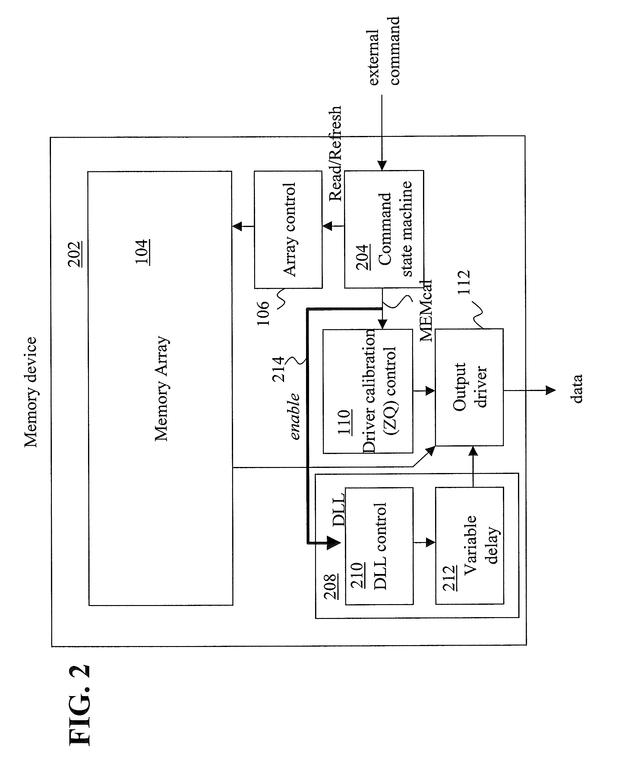
[0066]An exemplary embodiment includes a memory device that reduces power consumption by synchronizing a delay locked loop (DLL) in the memory device on a periodic basis. A new command is provided to instruct the memory device to perform the synchronizing of the DLL. Exemplary embodiments are contrasted to contemporary memory devices, where the DLL is updated on a continuous basis and consumes power on a continuous basis to perform the synchronization.

[0067]Another exemplary embodiment includes a memory device that improves data integrity by preventing data associated with a faulty command from being written to memory. This is performed without increasing the latency for memory write commands by processing a write command in a normal fashion and blocking a data path from being written using existing data masking circuitry if a parity error is detected on the address / command line.

[0068]Another exemplary embodiment includes a method of writing data masking bits without requiring a ded...


PUM


Abstract

An advanced memory having improved performance, reduced power and increased reliability. A memory device includes a memory array, a receiver for receiving a command and associated data, error control coding circuitry for performing error control checking on the received command, and data masking circuitry for preventing the associated data from being written to the memory array in response to the error control coding circuitry detecting an error in the received command. Another memory device includes a programmable preamble. Another memory device includes a fast exit self-refresh mode. Another memory device includes auto refresh function that is controlled by the characteristic device. Another memory device includes an auto refresh function that is controlled by a characteristic of the memory device.

Description

BACKGROUND[0001]This invention relates generally to memory within a computing environment, and more particularly to memory devices.[0002]Overall computer system performance is affected by each of the key elements of the computer structure, including the performance / structure of the processor(s), any memory cache(s), the input / output (I / O) subsystem(s), the efficiency of the memory control function(s), the main memory device(s), and the type and structure of the interconnect interface(s).[0003]Extensive research and development efforts are invested by the industry, on an ongoing basis, to create improved and / or innovative solutions to maximizing overall computer system performance and density by improving the memory devices utilized, in addition to the memory systems / subsystems making use of such devices. It is important that memory device improvements meet the increased performance, reduced power and increased reliability of future systems by integrating enhanced features and functi...

Claims


Application Information

Patent Timeline
Patent Type & Authority Applications(United States)
IPC IPC(8): G11C7/00G11C8/18H03M13/09G06F11/07G06F11/10
CPCG06F11/1028G11C2207/2254G11C7/1051G11C7/1066G11C7/1069G11C7/1078G11C7/109G11C7/22G11C7/222G11C11/401G11C11/406G11C11/40611G11C11/40615G11C11/40626G11C11/4076G11C11/4096G11C29/02G11C29/023G11C29/028G11C7/04
Inventor KIM, KYU-HYOUNCHIU, GEORGE L.COTEUS, PAUL W.DREPS, DANIEL M.GOWER, KEVIN C.HUNTER, HILLERY C.KILMER, CHARLES A.MAULE, WARREN E.
Owner GLOBALFOUNDRIES US INC
Learn More