
Exhaust purification apparatus for internal combustion engine

a technology for purifying apparatus and internal combustion engine, which is applied in mechanical equipment, machines/engines, electric control of exhaust treatment, etc., can solve the problems of nox purification rate, decreased supply pressure of urea aqueous solution supply pump, and inappropriate opening and closing, so as to reduce the nox purification rate and suppress the possibility of ammonia slip

Inactive Publication Date: 2011-03-10
TOYOTA JIDOSHA KK
View PDF12 Cites 9 Cited by
  • Summary
  • Abstract
  • Description
  • Claims
  • Application Information

AI Technical Summary

Benefits of technology

[0014]The present invention enables a decrease in NOx purification rate and possible ammonia slip to be suppressed.

Problems solved by technology

If a urea aqueous solution addition system is abnormal, the following problems may occur.
An excessive amount of urea aqueous solution may be added to increase the amount of ammonia slipping through the NOx catalyst or an excessively small amount of urea aqueous solution may be added to reduce an NOx purification rate.
Examples of abnormality of the urea aqueous solution addition system include crystallization of the urea aqueous solution, blockage of the addition valve by dirt or the like, inappropriate opening and closing of the addition valve, a decrease in the supply pressure of a urea aqueous solution supply pump, and time degradation of the addition system.
If the increase in the addition amount of urea aqueous solution fails to improve the actual NOx purification rate, the system is determined to be abnormal.

Method used


Image

  • Exhaust purification apparatus for internal combustion engine
  • Exhaust purification apparatus for internal combustion engine
  • Exhaust purification apparatus for internal combustion engine

Examples


Embodiment Construction

[0023]Embodiments of the present invention will be described below with reference to the attached drawings.

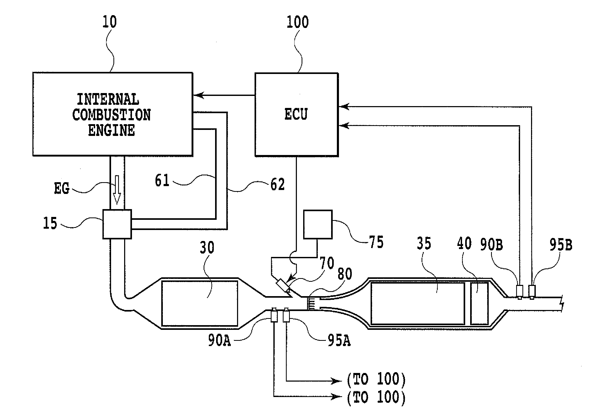
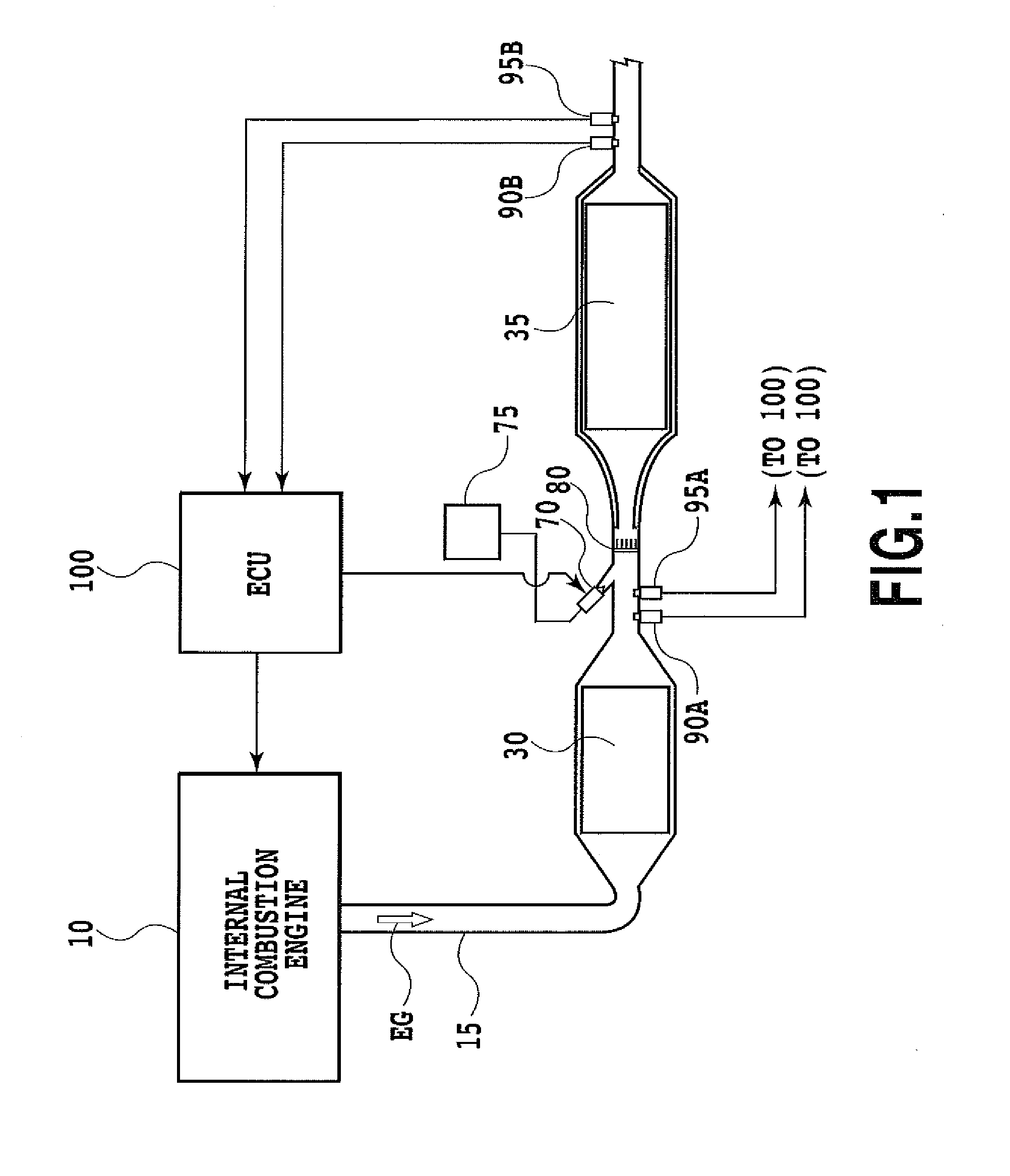
[0024]FIG. 1 is a diagram showing the configuration of an exhaust purification apparatus for an internal combustion engine according to an embodiment of the present invention.

[0025]An internal combustion engine 10 is, for example, a diesel engine. An exhaust passage 15 in the internal combustion engine 10 includes a DPF (Diesel Particulate Filter) 30 serving as a filter, and an NOx catalyst 35.

[0026]In the exhaust passage 15, a urea aqueous solution addition valve 70 and an addition valve downstream mixer 80 are provided between the DPF 30 and the NOx catalyst 35; the urea aqueous solution addition valve 70 serves as reducing agent adding means to add a urea aqueous solution to the exhaust passage 15, and the addition valve downstream mixer 80 is provided downstream of the urea aqueous solution addition valve 70 to mix exhaust gas EG with a urea aqueous solution.

[0027]Furthermo...


PUM


Abstract

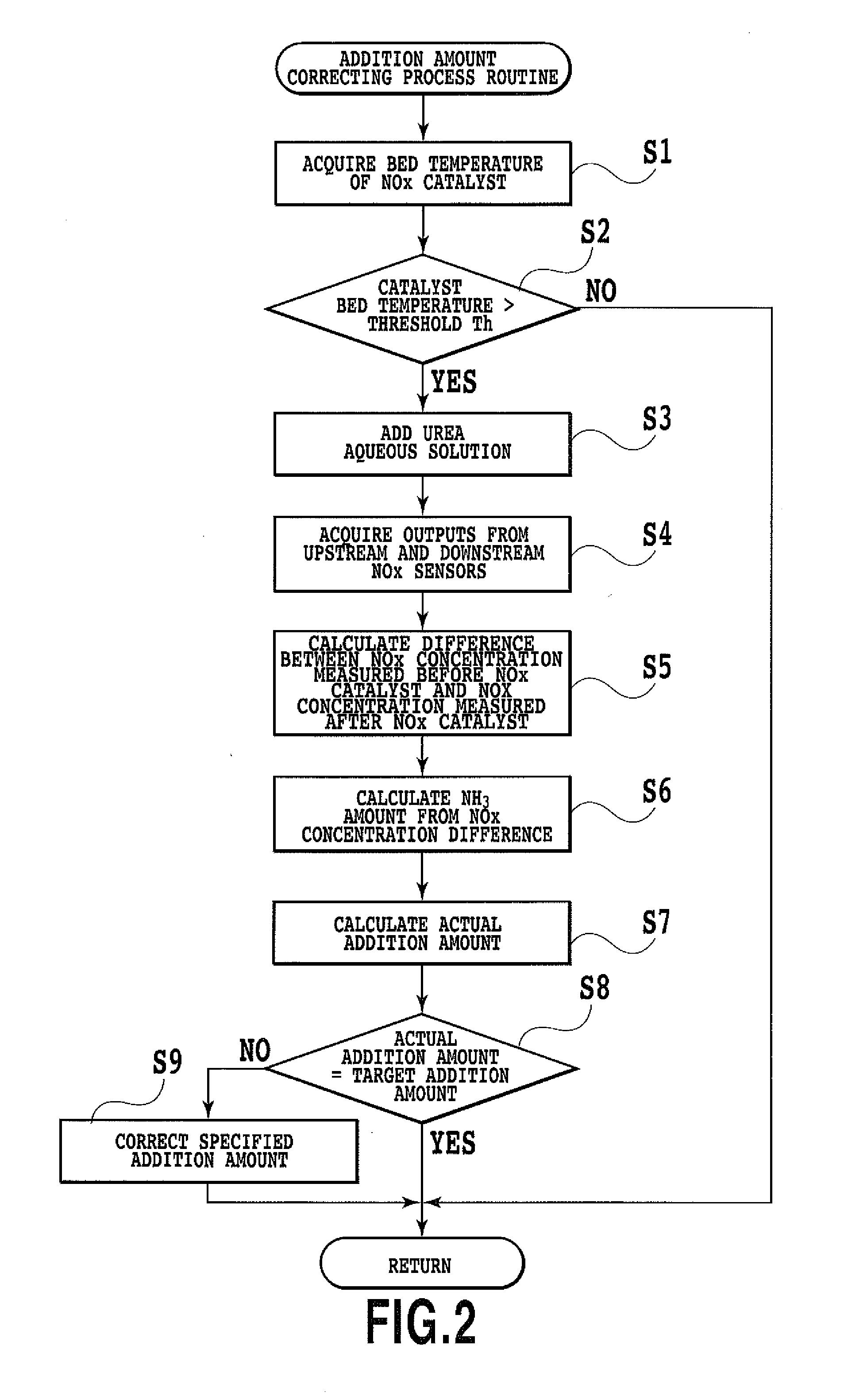
The present invention provides an exhaust purification apparatus for an internal combustion engine which enables a decrease in NOx purification rate and possible ammonia slip to be inhibited. The apparatus includes an NOx catalyst, a urea aqueous solution addition valve serving as reducing agent adding means, and NOx sensors provided an inlet and an outlet of the NOx catalyst, respectively. When the bed temperature of the NOx catalyst is in a predetermined high-temperature region in which the amount of ammonia converted into NOx increases relatively and an NOx purification rate decreases relatively, the apparatus uses outputs from the NOx sensors to perform correction such that the actual addition amount of the urea aqueous solution addition valve reaches a target addition amount.

Description

TECHNICAL FIELD[0001]The present invention relates to an exhaust purification apparatus for an internal combustion engine.BACKGROUND ART[0002]NOx purification systems are known which use a selective catalytic reduction (SCR) method of using ammonia to reduce and remove nitrogen oxide (hereinafter referred to as NOx) in exhaust gas from a diesel engine (see, for example, Patent Document 1). Such an NOx purification system generally supplies ammonia by adding a urea aqueous solution to a denitration catalyst (hereinafter referred to as an “NOx catalyst”) via an addition valve to hydrolyze the urea aqueous solution.[0003]If a urea aqueous solution addition system is abnormal, the following problems may occur. An excessive amount of urea aqueous solution may be added to increase the amount of ammonia slipping through the NOx catalyst or an excessively small amount of urea aqueous solution may be added to reduce an NOx purification rate. Examples of abnormality of the urea aqueous soluti...

Claims


Application Information

Patent Timeline
IPC IPC(8): F01N11/00F01N3/035F01N3/10F01N9/00
CPCF01N3/208F01N2560/026F01N2570/14F01N2610/02Y02T10/24F01N3/023F01N2560/021F01N2900/1602F01N2900/1616Y02A50/20Y02T10/12
Inventor ASAURA, SHINYAODA, TOMIHISATOSHIOKA, SHUNSUKESATO, MASAAKI
Owner TOYOTA JIDOSHA KK
Learn More