Pade' approximant based compensation for integrated sensor modules and the like

a sensor module and approximation technology, applied in the field of electronic systems, can solve the problems of insufficient interface directly with the electronic or other control system, distorted, and comparatively weak electric or other signals generated by the sensor in response to a given physical attribute that is being sensed (e.g., ) to achieve the effect of low cost mass production, high accuracy and reduced power consumption

Inactive Publication Date: 2011-03-10
SEMICON COMPONENTS IND LLC
View PDF12 Cites 10 Cited by
  • Summary
  • Abstract
  • Description
  • Claims
  • Application Information

AI Technical Summary

Benefits of technology

[0029]The present disclosure provides a nonlinearity compensation method and a corresponding structure that can be made highly accurate, can be adjusted with a program, and can be made flexible so as to be used in a wide range of applications while allowing for low cost mass production and reduced power consumption. Methods and structures disclosed herein allow for sensor calibration to take place as an integral part of nonlinearity compensation, where both functions may be implemented by the same circuit. Embodiments in accordance with the invention may be implemented as monolithic integrated circuits which use mostly analog techniques for providing signal conditioning that is free of digitization problems (e.g., quantization error and / or sample time hold up).

Problems solved by technology

Many sensing elements present unique requirements and limitations that need to be somehow circumvented or compensated for.
Often, the electric or other signal generated by a sensor in response to a given physical attribute that is being sensed (e.g., force, displacement, velocity, acceleration, temperature or any other physical parameter that can be detected and / or measured) is comparatively weak, distorted, or simply not adequate to interface directly with the electronic or other control system that is to use the sensor output signal.
The non-ideal response functions may be plagued by variation of response over different temperature ranges and / or by nonlinear response to linear change in the physical parameter being measured.
Although a number of different nonlinearity compensation techniques have been developed, they tend to be costly and time consuming to implement and frequently provide insufficient accuracy or suffer from other undesirable technical limitations.
Although the technique is effective to varying degrees, these source feedback techniques rely on manual, trial-and-error adjustments with use of potentiometers or selection of resistors with pre-selected values.
This kind of approach is not adequate to mass production where each sensor may need individual compensation and / or calibration.
Also, if fixed “average” resistor values are used for all sensors, accuracy is sacrificed because normal manufacturing variations in the sensing elements are not compensated.
However, these approaches do not simultaneously address the nonlinearities that are inherent within the sensing ranges of many sensors, regardless of temperature variation.
Although they can be flexible and potentially accurate, implementation of these solutions normally requires provision of an adjacent microcomputer or a digital signal processor (DSP), and a substantial quantity of memory, all this increasing complexity, power consumption and cost.
This tends to introduce speed limitations due to the sampling periods of the A / D converters.
This also tends to introduce potential aliasing problems, and quantization errors.

Method used


Image

  • Pade' approximant based compensation for integrated sensor modules and the like
  • Pade' approximant based compensation for integrated sensor modules and the like
  • Pade' approximant based compensation for integrated sensor modules and the like

Examples


embodiment 1000

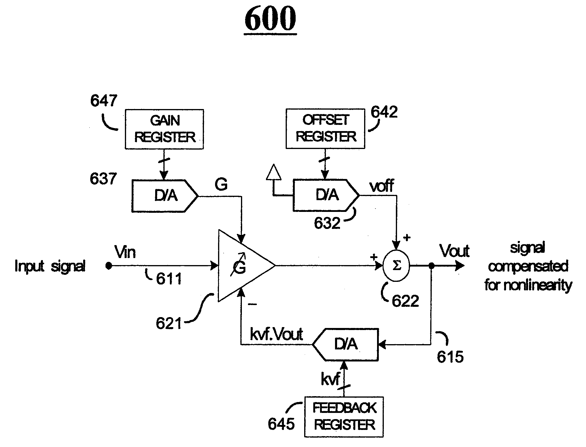
[0110]FIG. 10 is a schematic of a digitally-implemented, first order Padé Approximant compensating circuit 1000. FIG. 10 shows a digital embodiment 1000 that is roughly equivalent to the analog embodiment of FIG. 6. Vin may be converted to digital format if not already in that format, by the front end A / D converter. Vout may be converted to analog format by the back end D / A converter if such an analog output format is needed. Otherwise, the already digitized Vout signal may be serially output from the module via the serial data link. (See again the I / O interface 1290 of FIG. 12.)

[0111]FIG. 11 is a block diagram of a sensor and sensor-containing environment in accordance with the invention.

[0112]FIG. 12 is a schematic of yet another sensor module 1201 in accordance with the disclosure. The to-be-sensed physical parameter, P(t), is coupled into the module 1201 from the external environment 1200. Coupling may be accomplished wirelessly, such as by magnetic and / or electrostatic coupling...

embodiment 1500

[0129]FIG. 15 is a schematic of an embodiment 1500 having a digital input multiplier (the leftmost D / A converter) at the front end of the mapping circuit and a further digital multiplier receiving feedback from the output.

embodiment 1600

[0130]FIG. 16 is a schematic of a further embodiment 1600 having a 3-input multiplier at the front end of the mapping circuit and a 3-input summer before the variable gain amplifier.


PUM


Abstract

Methods and systems using Pade' Approximant expansion ratios provide mappings between nonlinear sensors and a more linear output domain. The method includes a method of converting an input digital signal having a nonlinear dependency on a physical variable into an output digital signal that exhibits a substantially linear dependency with respect to the variable is disclosed. The method includes: (a) multiplying the input digital signal by a variable multiplying factor to thereby generate a multiplied digital version of the input signal; (b) adding to the multiplied digital version of the input signal, a predefined digital offset signal to thereby produce the output digital signal; (c) multiplying the output digital signal by a predefined feedback gain correction factor to thereby produce a digital feedback signal; (d) using the digital feedback signal to produce the variable multiplying factor.

Description

[0001]The present application is a divisional application of the co-pending U.S. patent application Ser. No. 12 / 112,256, filed Apr. 30, 2008, which is a divisional application of Ser. No. 11 / 700,475, filed Jan. 30, 2007, now issued as U.S. Pat. No. 7,378,858, which is a divisional application of Ser. No. 10 / 845,681, filed May 13, 2004, now issued as U.S. Pat. No. 7,190,178. The disclosures of all related applications are incorporated herein by reference, as if fully stated here, for all purposes.FIELD OF DISCLOSURE[0002]The present invention relates generally to electronic systems which compensate for analog transducer nonlinearities and / or temperature drift.[0003]More specifically, the invention relates to integrated sensor modules where a transducer is packaged together with compensating means such as electronic compensating circuitry.CROSS REFERENCE TO PATENTS[0004]The disclosures of the following U.S. patents are incorporated herein by reference:[0005](A) U.S. Pat. No. 6,198,296...

Claims


Application Information

Patent Timeline
Patent Type & Authority Applications(United States)
IPC IPC(8): G06F7/44
CPCG01D3/022G01L19/04G01L1/2281G01D18/008
Inventor LARAIA, JOSE MARCOSTAVEIRA, JOSE G.MOEHRKE, ROBERT P.
Owner SEMICON COMPONENTS IND LLC
Why Eureka
Try Eureka