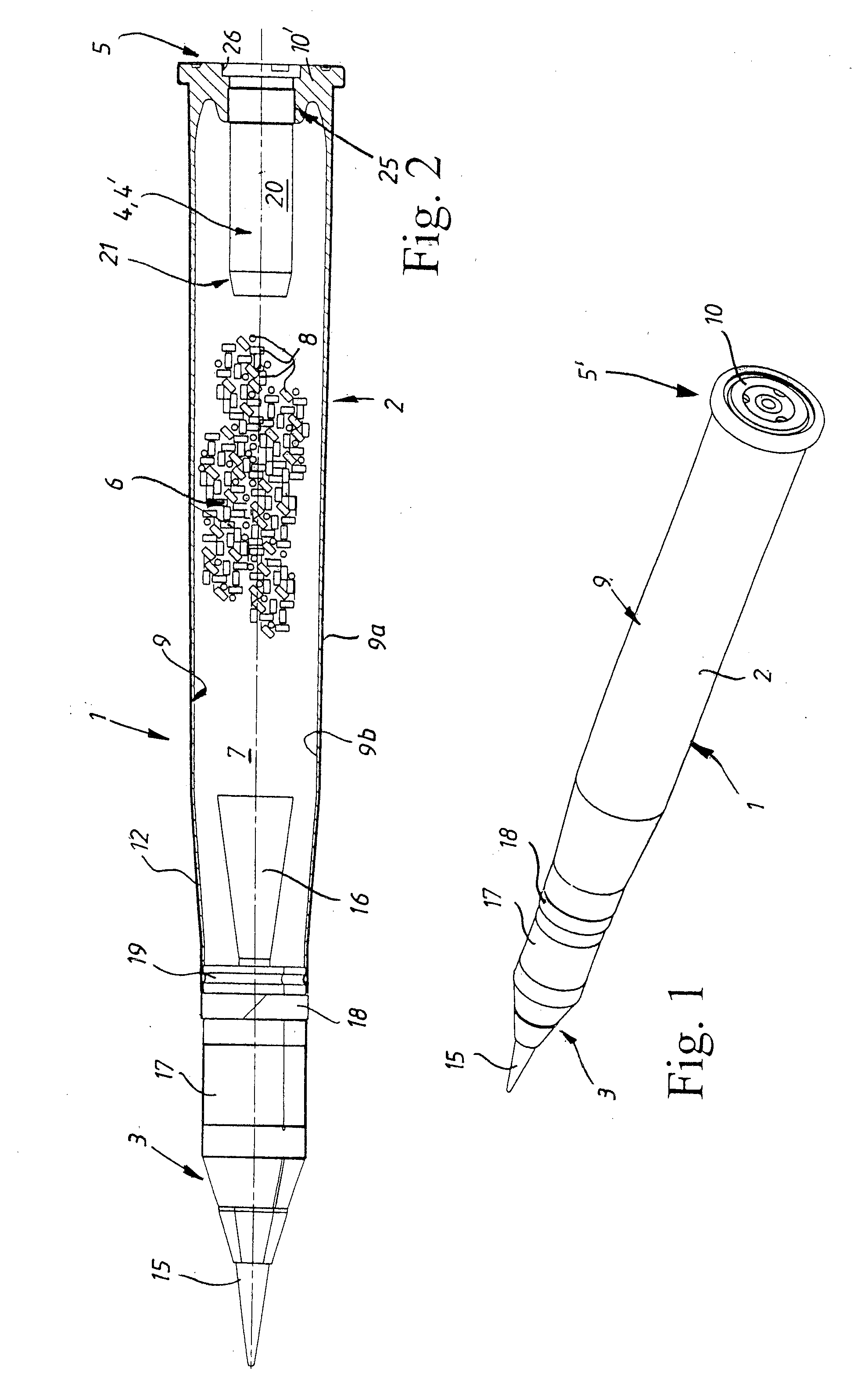
Plasma generator comprising sacrificial material and method for forming plasma, as well as ammunition shot comprising a plasma genrator of this type

a plasma generator and sacrificial material technology, applied in the direction of blasting cartridges, weapons, ammunition, etc., can solve the problems of increasing increasing the total weight, and reducing the maximum size so as to facilitate the plasma process and the ignition of the propellent charge. , the effect of reducing the weigh

Inactive Publication Date: 2011-03-17
BAE SYST BOFORS
View PDF4 Cites 9 Cited by
  • Summary
  • Abstract
  • Description
  • Claims
  • Application Information

AI Technical Summary

Benefits of technology

[0090]The inevitably high plasma temperatures in the plasma generator make it necessary for the combustion chamber channel walls to be protected by the insertion of an insert made of, or by the lagging of the combustion chamber channel walls with, a highly heat-resistant ceramic. Moreover, the ceramic is significantly more leak-tight than an insulation made of, for example, fibreglass, since fibreglass insulation more easily lets through the current in the space between the fibreglass threads.
[0091]Via the shrink-fastening of the ceramic inside the combustion chamber channel according to the invention, by the clearances, which are otherwise formed by material irregularities and fault tolerances, between the ceramic and the walls of the combustion chamber channels are removed or at least heavily reduced and by which shrink-fastening the ceramic insert / lagging / tube becomes so precompressed by the contraction of the enclosing combustion chamber during the shrinkage that the tensile stresses which subsequently arise in the ceramic in the formation of the plasma are less than the precompression or are so much counteracted that the resulting stresses in the ceramic are lower than the maximally permitted tensile stresses for the ceramic, the problems with easy cracking of the ceramic under the very high tensile stresses which would arise in the ceramic in the formation of one or more plasma(s) are satisfactorily resolved.
[0092]Since the improved plasma generator allows a plurality of successive energy pulses, which are withstood by the ceramic in the combustion chamber by virtue of its precompressed shrink-fastening, which gives an even higher temperature, and hence pressure, than was previously possible, a faster and more complete propellent charge combustion can be obtained and then, moreover, by more modern, more energetic propellent charges, since the propellants of these more modern propellent charges can now not only be ignited, but can also be converted into even smaller molecules than previously, whereupon yet more energy is extracted from the same propellent charge quantity, so that the maximally possible muzzle velocity for the particular barrel weapon therefore increases.
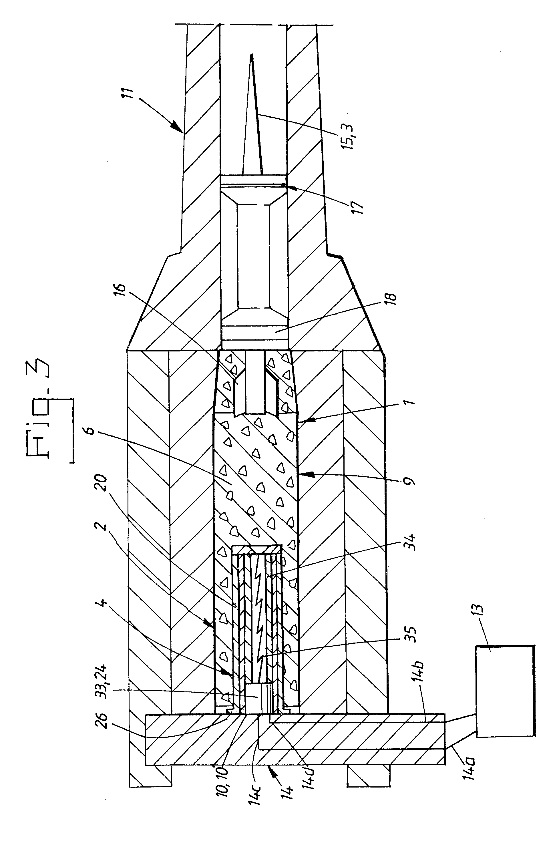
[0093]The previous problems of the ceramic preventing ablation from the combustion chamber channel walls and of the glow wire, which acts as a catalyst for initiation of the plasma process, burning up under the first energy pulse and therefore substantially impeding or wholly preventing a continued plasma formation and a resumed electrical energy supply should the plasma cool or die down are tackled according to the invention via the placement of the specially selected gasifiable sacrificial material inside the ceramicized combustion chamber channel.
[0094]The chosen sacrificial material is not gasified wholly under the first energy pulse, but is evaporated layer-by-layer, surface coating by surface coating, see FIG. 11, for each new electrical energy pulse, in which the sacrificial material, upon combustion of the same, releases molecules, atoms and / or ions with low molecular weight, i.e. the molecules and the atoms have a lower weight (≦30 u) than the heavier metal ions (>30 u) which are normally utilized in known plasma generators, which light molecules, atoms and / or ions participate in and facilitate the plasma process and the ignition of the propellent charge. Even if the plasma is allowed to cool between the energy pulses, the plasma generator can nevertheless be fired, since the sacrificial material remains, such that new layers or surface coatings can be gasified by the next energy pulses.
[0095]In, for example, a preferred embodiment in which the sacrificial material is comprised of a polymer, such as a plastic tube, for example a polyethylene tube, molecules and atoms of the said polymer, which are ionized upon the formation of the plasma, are obtained, which ions primarily comprise various carbon and hydrogen ions, which are lighter than the metal ions formed by the electrical conductor.

Problems solved by technology

The increase in velocity which is thereby possible is, however, relatively limited.
There can also be a problem in being able to fill conventional ammunition shots with all the quantity of propellent charge which is required to attain the desired muzzle velocity and, at the same time, to accommodate the actual projectile without heavily increasing the total weight of the ammunition shots.
Thus the optimal propellent charge, regardless of the size of the propellent charge and the attained propulsion velocity of the propellent charge, must burn as fast as the time it takes to drive the projectile out of the barrel, so that a limiting factor for the maximum size of the propellent charge is the barrel length of the weapon.
At the same time, it is also the case, of course, that the longer is the barrel, the heavier and more unwieldy is the weapon, so that the desired manoeuvrability of the weapon and the total weight of the weapon in turn limit the optimal barrel length and the material length of the barrel.
Yet, in spite of the aforementioned efforts to improve the current conventional propulsion methods and the propellent charges which are utilized for these, the practically possible upper limit for the muzzle velocity in the conventional barrel weapons, and then also for the chemically progressive, inhibited and perforated multihole gunpowders, has been reached at about 1500-1800 m / s.
This is due to the fact that the chemical progressivity of the currently known propellent charges has an upper limit and since the multiperforation of the constituent propellent charges cannot currently be carried out, however finely powdered.
Moreover, these measures, inclusive of the said inhibition, are not very easy to pre-calculate and execute such that the desired pressure curve, for each fired type of propellent charge, always remains exactly the same each time.
It will be appreciated that the firing accuracy of the projectile is impaired if the muzzle velocity cannot always be predetermined for each fired shot.
Due to the very high temperature and also the very high internal pressure inside the plasma generator, the combustion chamber of the plasma generator, as well as the barrel, will be subjected to very large heat and load stresses.
The long pulse length is disadvantageous, however, with respect to the supplied greater quantity of energy for the acceleration of the projectile, so that a solution to this heat problem is to provide the channel walls of the combustion chamber with an internal, highly heat-resistant insulating material, for example a ceramic which is also electrically insulating.
The ceramics are characterized by a relatively good compressive strength, but they have a low strength otherwise.
If there happens to be any clearance at all between the ceramic and the walls of the combustion chamber channels, or if the combustion chamber channels yield, i.e. are expanded, to the pressure, tensile stresses will inevitably arise in the ceramic.
In the aforementioned plasma jet burner, U.S. Pat. No. 4,957,035, these tensile stresses would easily tear apart the ceramic and cause serious leakage of heat, current, voltage and / or plasma, resulting in inevitable damage to the weapon, if the strength of the plasma jet burner had not been mechanically improved via the axial force with which the conical plasma jet burner is screwed into a corresponding conical and inflexible space and is thus clamped tight.
The intention is that this mechanical squeezing into the conical space of the plasma jet burner, at least to a certain extent, will attempt to counteract the said tensile stresses in the ceramic, which has not, however, been wholly successful.
Despite these measures, this conical screw fastening nevertheless gives an unsatisfactory result.
In particular, the problems with the clearances between the ceramic and the walls of the combustion chamber channels, which clearances are formed by material irregularities and fault tolerances, and with the fact that the mutually interacting conical components must be very precisely made in order to fit together without play, thereby making the components expensive to produce, still persist.
The conical screw fastening therefore constitutes an expensive and, in production engineering terms, time-consuming and complicated way of solving the problems with the tensile stresses in the ceramic.
Moreover, even with just somewhat longer pulse lengths, of just a few milliseconds, such extremely high temperatures arise that the plasma generator risks suffering damage in spite of the ceramic.
The aforementioned conical construction quickly becomes leaky and thus unusable, so that the construction constitutes a disposable weapon.
A further basic problem with the currently customary ETC weapons is that they utilize the barrel as a counter electrode, so that these constructions also impart current or voltage to the actual barrel and thus to other basic parts of the particular weapon system.
In addition to obvious drawbacks with this, such as the risk of personal injury due to the electrical danger and short-circuiting of the weapon system, it will be appreciated that there is a substantial risk of a metallic cartridge case being welded fast in the barrel when current and voltage is transmitted to the weapon.
Moreover, sensitive electronic equipment can be damaged by unwanted electrical transmissions and ensuing magnetic fields.
In one of the shown embodiments, the said metallic cartridge case is instead made of a non-conductive material, but as the barrel is utilized as a counter electrode the barrel will continue to be live and the cartridge case is in this case at risk of fusion.
The whole of the weapon is therefore at risk of becoming a disposable weapon which can only be fired once.

Method used


Image

  • Plasma generator comprising sacrificial material and method for forming plasma, as well as ammunition shot comprising a plasma genrator of this type
  • Plasma generator comprising sacrificial material and method for forming plasma, as well as ammunition shot comprising a plasma genrator of this type
  • Plasma generator comprising sacrificial material and method for forming plasma, as well as ammunition shot comprising a plasma genrator of this type

Examples


second embodiment

[0141]The plasma generator 4′ according to this second embodiment, FIG. 9, further comprises a somewhat differently configured centre electrode 24′. The rear metallic centre connector 33′ is in FIG. 9 shown somewhat axially displaced inside the ceramic tube 23 in the direction of the front cylindrical body 28, with the formation of an empty space 43 towards the rear end 22 of the combustion chamber 20, which empty space 43 is intended for the male connector 49 of the back piece 14, i.e. the input conductor 14c (schematically shown in FIG. 9 and FIG. 10). In addition, the said centre connector 33′ comprises a rear centric cavity 44 extending axially inwards, the inner surface 44′ of which cavity 44 is lined with the same type of lamellar contact strip 45, and with corresponding function, as the lamellar contact strip 42 of the flange 26′, yet with the difference that the male connector 49 disposed on the back piece 14, which is schematically shown in FIG. 9 and FIG. 10 and acts as th...

first embodiment

[0146]One difference with the configuration of the lamellar contacts 42′, 45′ which is shown in FIG. 9 compared with the first embodiment shown in FIG. 4 is that the lamellar contact strips 42, 45 in FIG. 9 provide the facility for the connectors 48, 49 and the lamellar contact strips 42, 45 to be able to slide relative to each other over a certain axial distance and yet to be in fixed contact by virtue of the sliding surface, interacting between them, of the respective part. This configuration of the contact surface naturally provides a considerably larger contact surface than is the case with the customary contact surfaces of the point-contact or surface-contact type, so that the current transfer is spread over this larger contact surface, so that the current transfer is facilitated and the risk of a light arc is eliminated, thereby preventing welding / burning fast even in the event of a number of pulses.

[0147]Functional Description

[0148]The production, working and use of the plasm...


PUM

PropertyMeasurementUnit
melt temperatureaaaaaaaaaa
temperatureaaaaaaaaaa

Abstract

The invention relates to a plasma generator (4, 4′) for electrothermal and electrothermal-chemical weapon systems, which plasma generator is intended to deliver at least one energy pulse for the formation of a plasma for accelerating a projectile (3) along the barrel (11) of the weapon system. The plasma generator comprises a combustion chamber (20) with a combustion chamber channel (20′), a centre electrode (24, 24′) disposed inside the combustion chamber channel, which combustion chamber and centre electrode are electrically conductive, and a ceramic tube (23) arranged between the combustion chamber and the centre electrode. The ceramic tube is shrink-fastened into the combustion chamber, and the plasma generator further comprises a polymeric sacrificial material (34, 34′), which is gasifiable by the energy pulse. The invention also relates to a method for making the plasma generator form a plasma, and an ammunition round having a plasma generator according to the invention.

Description

TECHNICAL FIELD[0001]The present invention relates to a plasma generator for electrothermal and electrothermal-chemical weapon systems, which plasma generator is intended to deliver at least one energy pulse for the formation of a plasma for accelerating a projectile along the barrel of the weapon system, which plasma generator comprises a combustion chamber having an axial combustion chamber channel, a centre electrode disposed inside the combustion chamber channel, which combustion chamber and centre electrode are electrically conductive, as well as a ceramic tube, arranged between the combustion chamber and the centre electrode disposed inside the combustion chamber, for insulating the centre electrode from the combustion chamber.[0002]The present invention also relates to a method for making a plasma generator for electrothermal and electrothermal-chemical weapon systems form at least one plasma, which plasma is intended to accelerate a projectile along the barrel of the weapon ...

Claims


Application Information

Patent Timeline
Patent Type & Authority Applications(United States)
IPC IPC(8): F42B5/02B23P11/02
CPCY10T29/49863F42B5/08F42B3/14
Inventor GUSTAVSSON, LENNARTSTARK, OLA
Owner BAE SYST BOFORS
Why Eureka
Try Eureka