Drying heater, heating unit for drying laundry using the same, drying control system and control method thereof

a technology for drying heaters and heating units, which is applied in the direction of ohmic resistance heating, home appliance efficiency improvement, sustainable buildings, etc., can solve the problems of loss of heat insulation cost, structural limitation in order to keep a certain distance between internal components, and limited heat exchange through contact surfaces. , to achieve the effect of reducing the burden of electric charges, reducing the amount of electric power consumption and power line consumption, and increasing heat exchange efficiency

Inactive Publication Date: 2011-03-17
AMO GMBH
View PDF23 Cites 25 Cited by
  • Summary
  • Abstract
  • Description
  • Claims
  • Application Information

AI Technical Summary

Benefits of technology

[0111]As described above, the present invention uses a drying heater that can increase a heat exchange efficiency with air, and heat air at a sufficient temperature that can dry washes with a low temperature heat generation operation, to thereby remarkably reduce electric power consumption and an amount of consumption of power lines which is required for drying the washes, to thus reduce burden of electric charges and prevent fire outbreak due to overload, when using electric products.
[0112]In addition, the present invention can remarkably shorten a period of time for which air is heated up to a temperature necessary for drying washes, to thereby shorten time which is taken for drying the washes, and reduce electric power consumption in proportion to the shortened drying time.
[0113]In addition, the present invention can use synthetic resin materials as materials of components in the neighborhood of a heating unit as well as those of a blower fan and a duct casing for use in a drying-purposed heating unit since a heat generation temperature of a drying heater is low, to thereby a manufacturing cost of a washing machine or a laundry drying machine.
[0114]In addition, the present invention employs a strip style surface-shaped heat generation member made of a metal thin film whose temperature response feature is fast, which is driven at low temperature, and whose heat exchanged area is large, as a heat generation member, to thus heighten a heat exchange efficiency with air, to thereby prevent inefficient electric power consumption which may be caused by high temperature heat generation by supplying air of temperature sufficient for drying washes even employing a low temperature heat generation, and to accordingly reduce electric power consumption by optimizing electric power consumption.

Problems solved by technology

In addition, in the case of the sheath heater, a contact surface through which is heat exchanged with external air is limited as nothing but a surface of the metal protective tube.
It can be seen that a heat insulation structure is needed around the heater from the temperature rise when considering that the maximum heat generation temperature of the sheath heater is 750° C. Further, it can be seen that structural limitation exists in order to keep a certain distance between internal components.
As a result, the sheath heater may cause a loss of heat insulation cost and an increase in size of the structure.
Therefore, the conventional laundry drying machine adopting the sheath heater has problems that a drying time increases and an amount of electric power consumption increases and thus a very expensive electricity use fare should be paid due to a slow temperature rise in the sheath heater under the conditions that optimum temperature should be maintained and a temperature rise and a cooling operation should be repeated.
In addition, the drying-purposed heating unit 1 may give damage to the drive motor of the blower fan 3 by heat that is transferred through the duct casing 2 if the drive motor of the blower fan 3 is driven for long hours and then the sheath heater 4a is not sufficiently cooled for cooling the sheath heater 4a after laundry has been completely dried.
As a result, the manufacturing cost of washing machines or laundry drying machines may be additionally increased.
However, in the case that the coil-shaped heat generation element is used, the U.S. Pat. No. 4,617,547 has problems that may cause an increase in a manufacturing cost due to using the plurality of the insulators, and a low safety and a low efficiency due to the high temperature heat generation and the high power consumption.
However, since the drying apparatus of the Korean Patent Laid-open Publication No. 2006-14485 includes the surface-shaped heat generation element incorporated in the inside of the drying space, it may not be easily applied to a general laundry drying machine or wash drier.
However, since most of the high temperature heat-generation-style heat generation elements are made of alloy expensive metal such as Ni, a manufacturing cost may increase and high electric power consumption may be required.

Method used


Image

  • Drying heater, heating unit for drying laundry using the same, drying control system and control method thereof
  • Drying heater, heating unit for drying laundry using the same, drying control system and control method thereof
  • Drying heater, heating unit for drying laundry using the same, drying control system and control method thereof

Examples


second experimental example

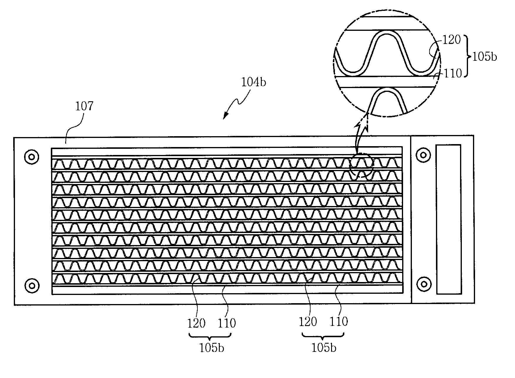
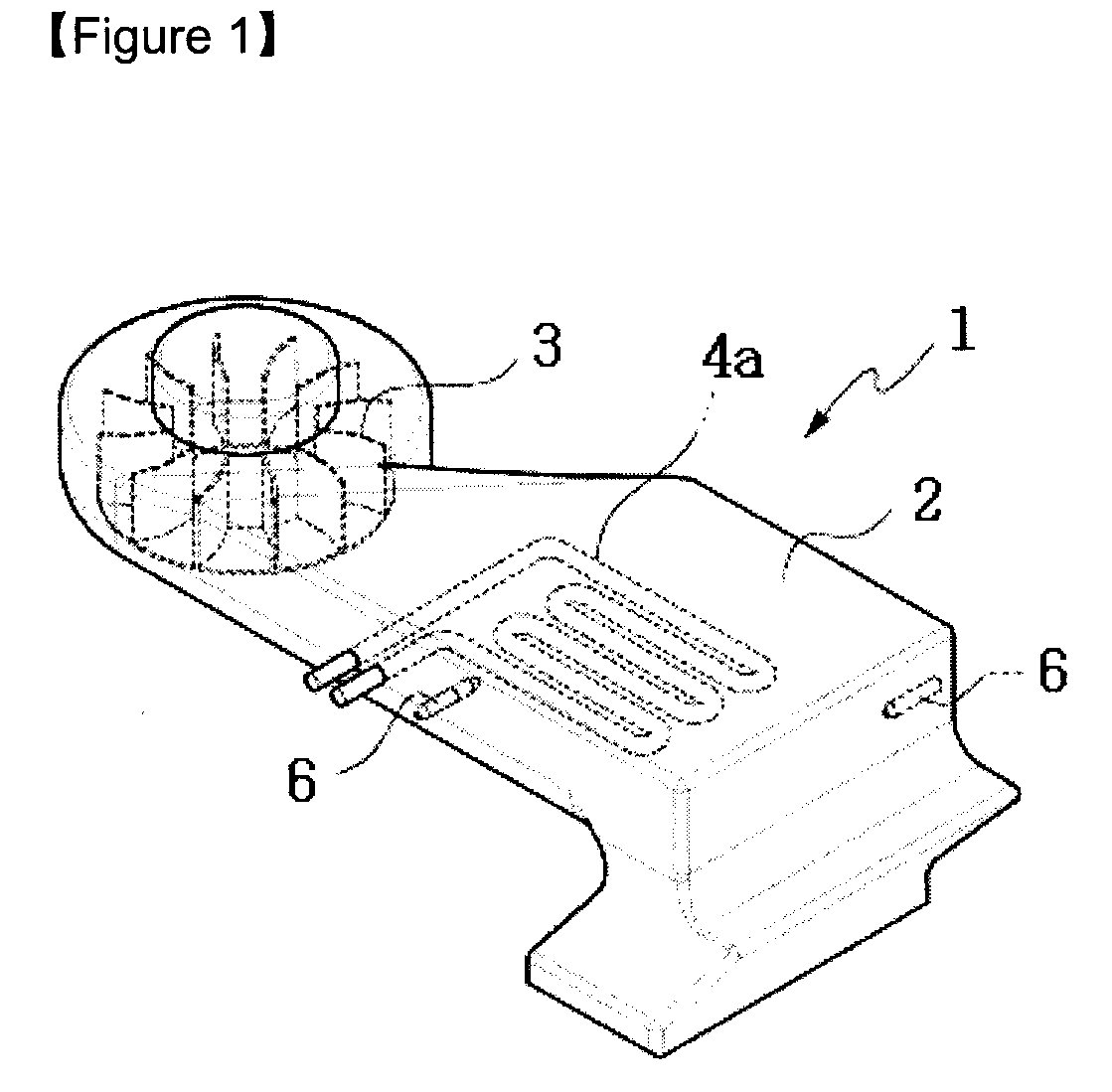
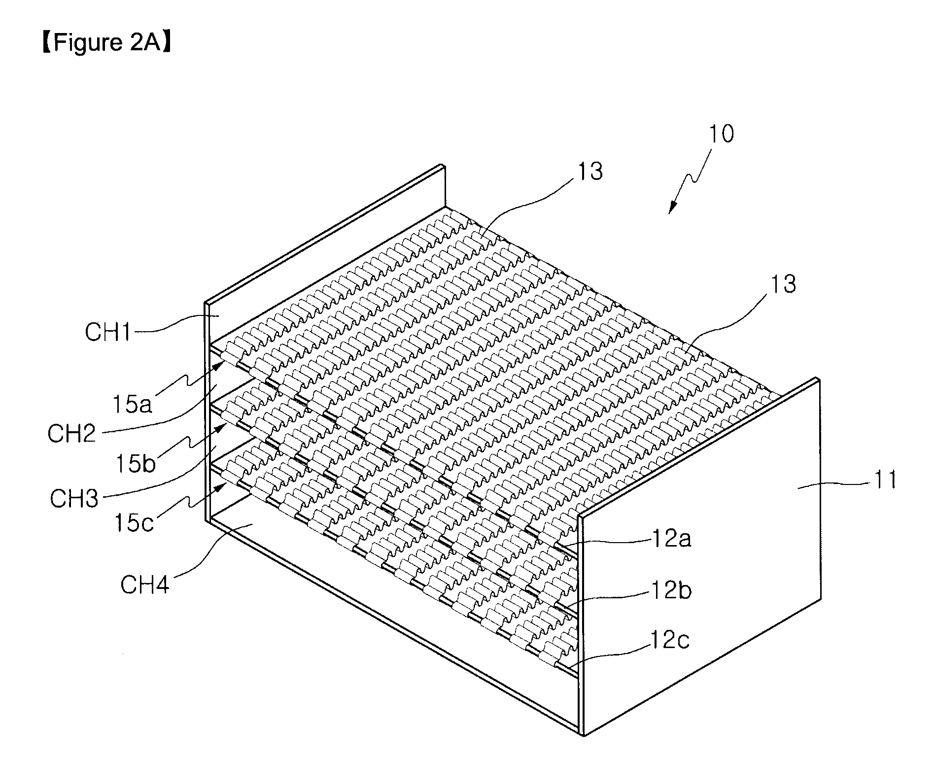
[0205]In the second experimental example, the drying heater employing the strip style surface-shaped heat generation members made of metal thin plates according to the embodiment of the present invention illustrated in FIG. 2A is used and is driven by a double drive power supply mode shown in FIGS. 5 and 6, but the sheath heater of FIG. 1 in the conventional case is used and driven by a single drive power supply mode of 220V in the same manner as the first experimental example.

[0206]For a comparison experiment, in the case of the embodiment of the present invention, a sheath heater and a drive power supply of a laundry drying machine (Model No. WD-DR351S) of LG Electronics Co., Ltd. which is a Korean electronics company are replaced by the drying heater and the double drive power supply mode according to the embodiment of the present invention. In the conventional case, the laundry drying machine (model No. WD-DR351S) of LG Electronics Co., Ltd., uses the sheath heater and the singl...

second embodiment

[0218]FIG. 9A is a schematic block diagram showing a drying control system of a laundry drying machine according to a second embodiment of the present invention, and FIG. 10 is a flowchart view for explaining a drying control method of the drying control system illustrated in FIG. 9A.

[0219]Referring to FIG. 9A, the drying control system of the laundry drying machine according to the second embodiment of the present invention includes: a key input unit 21 having a number of keys for inputting user's request commands; a temperature sensor 22 for detecting a drum internal temperature (T) of the laundry drying machine according to an operation on / off command which is input via the key input unit 21; and a controller (CPU (Central Processing Unit)) 23 which generates a heater control signal for driving first and second heaters (H1 and H2) 10a and 10b and simultaneously a blower motor driving signal for driving a blower fan 103, based on the current drum internal temperature (T) detected ...

third embodiment

[0246]FIG. 9B is a schematic block diagram showing a drying control system of a laundry drying machine according to a third embodiment of the present invention.

[0247]There is a difference that, in the second embodiment, the first and second heaters 10a and 10b are connected in parallel with each other, but in the third embodiment, the first and second heaters 10a and 10b are connected in series with each other.

[0248]That is, in the third embodiment, the first and second heaters 10a and 10b are connected in series with each other between the single drive power supply (AC 220V) 26 and the ground, and a switching unit 29 is connected to the single drive power supply (AC 220V) 26 selectively at one end 31 of the second heater 10b and a connection point 30 between the first and second heaters 10a and 10b.

[0249]The controller (CPU) 23 controls the heater control signal to be applied to the switching unit 29 according to the drum internal temperature T similarly to the second embodiment. ...


PUM


Abstract

Provided is a drying heater, a heating unit for drying laundry using the same, a drying control system and control method thereof that reduces electric power consumption of the drying heater to supply high temperature dry air to the inside of a drum in a washing machine or a laundry drying machine, to thus simplify structure of the drying heater and reduce a manufacturing cost. The drying control method includes the step of applying a first electric power from a first drive power supply to a drying heater when a drum internal temperature is lower than a preset temperature, and applying a second electric power from a second drive power supply which is relatively smaller than the first electric power to the drying heater when the drum internal temperature is higher than the preset temperature. The drying heater includes a surface-shaped heat generation member made of a low thermal density strip style metal thin plate.

Description

TECHNICAL FIELD [0001]The present invention relates to a drying heater, a heating unit for drying laundry using the same, a drying control system, and a control method thereof. More particularly, the present invention relates to a drying heater, which reduces power consumption of the drying heater to supply high temperature dry air to the inside of a drum type tub (which may be called a drum hereinafter) in a washing machine having a drying function or a laundry drying machine, and simplifies structure of the drying heater, and thus reduces a manufacturing cost of the drying heater, a heating unit for drying laundry using the same, a drying control system and a control method thereof.BACKGROUND ART[0002]Usually, a washing machine is equipment for removing stains, dregs or pollutants which are stuck to clothes or bedclothes, by the action of detergents and water in a washing tub which uses torque of an electric motor, and performs a washing operation, a rinsing operation, and a dehyd...

Claims


Application Information

Patent Timeline
Patent Type & Authority Applications(United States)
IPC IPC(8): H05B3/02
CPCD06F58/26D06F2058/289D06F58/28D06F2105/28D06F58/48D06F2103/32Y02B40/00
Inventor YANG, JAE SUKLIM, HYUN CHULJEONG, SANG DONGJANG, SOUNG HOKIM, MYOUNG SOOKWON, SOONN KIYANG, SUNG CHUL
Owner AMO GMBH
Why Eureka
Try Eureka