Energy saving extra-low voltage dimmer and security lighting system wherein fixture control is local to the illuminated area

Inactive Publication Date: 2011-03-17
BONDY MONTGOMERY C +3
View PDF5 Cites 198 Cited by
  • Summary
  • Abstract
  • Description
  • Claims
  • Application Information

AI Technical Summary

Problems solved by technology

With respect to existing dimming methods, there are none available on the market for extra-low voltage lighting at the time of this application.
Prior to the Bondy et al system, attempts were made to find a practical and effective method for dimming extra-low voltage outdoor landscape luminaires, however as will be seen, none of the methods proved to have merit.
The result was not satisfactory.
With wire runs in place the lamps dimmed unevenly; some with longer runs were so dim as to be totally ineffective.
With this configuration of equal lengths of supply wire, all lamps dimmed equally and therefore did not produce the desired result since various light locations required differing light outputs.
In fact, conductors could produce different levels of dimming if they were purposely cut to different lengths, which was a very complex process and only proved the power losses.
Other problems included a very noisy power supply with attendant power losses.
The conductor losses were very large with the most severe losses on longer runs.
The use of the line voltage primary dimmer resulted in again far too much power loss.
Precise control of lamp output was in every case a complex calculation.
Again, with noise and heat losses in the transformer added to the other losses above, the power losses were over 25 percent.
A third method would be to place the dimmers at the power supply, but again the line losses were excessively high.
The voltage through the secondary transmission conductors was low enough to cause as much undesired dimming effect in line losses as the dimmer itself.
A line voltage (120 volts AC) system could be made to function in a similar manner as the Bondy et al system, but the expense woul

Method used


Image

  • Energy saving extra-low voltage dimmer and security lighting system wherein fixture control is local to the illuminated area
  • Energy saving extra-low voltage dimmer and security lighting system wherein fixture control is local to the illuminated area
  • Energy saving extra-low voltage dimmer and security lighting system wherein fixture control is local to the illuminated area

Examples


first embodiment

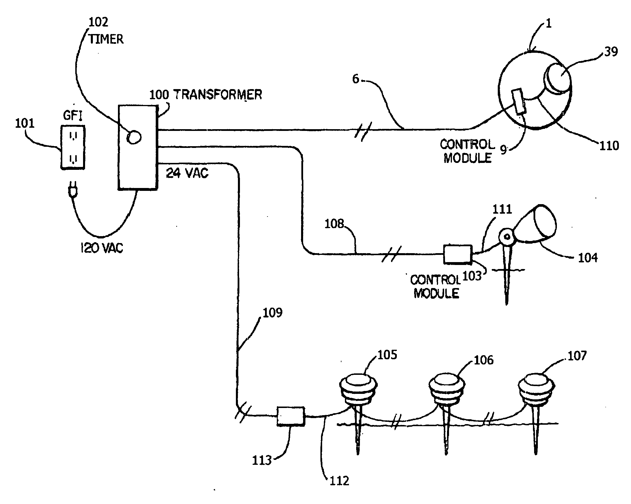
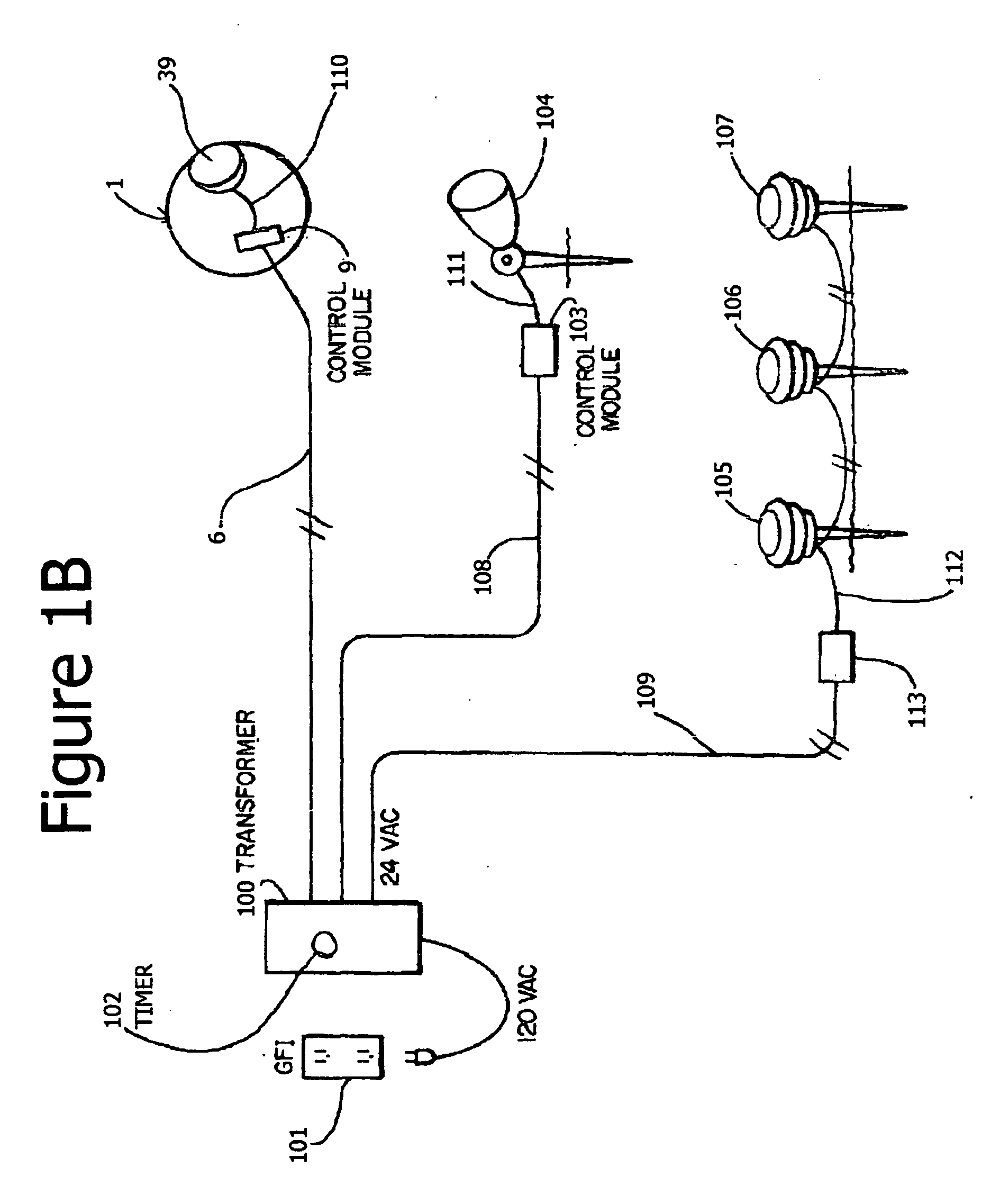
[0627]In FIG. 1B, the configuration of the first embodiment consists of the power supply transformer (120 volts AC) 100 connected by secondary transmission conductors 6 to the Control Module 9 (internal to the luminaire 1). The Control Module 9 is connected to the lamp 39 within luminaire 1 via power conductors 110.

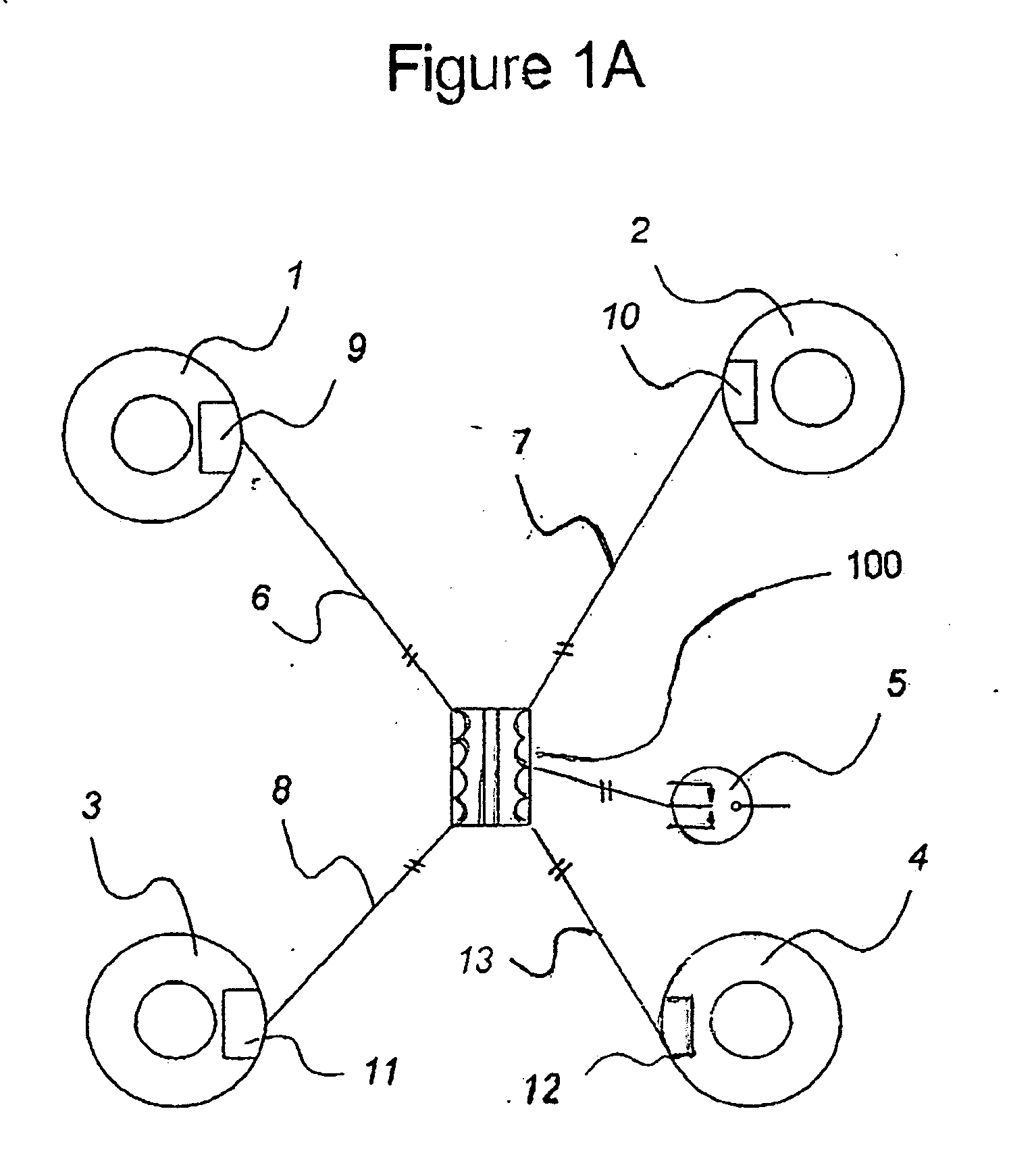
[0628]In a multi-luminaire configuration of this embodiment, as illustrated in FIG. 1A described above, additional luminaires 2, 3, 4 with their own individual Control Modules (internal to the luminaire 2, 3, 4) 10, 11, 12 are added and connected to the power supply transformer (120 volts AC) 100 with secondary transmission conductors 7, 8, 13.

second embodiment

[0629]In FIG. 1. B, the configuration of the second embodiment consists of the power supply transformer (120 volts AC) 100 connected by secondary transmission conductors 108 to the Control Module 103 (external to the luminaire) in close proximity to an extra-low voltage luminaire 104 of other manufacture, in which the lamp does not exceed 50 watts. From the external Control Module 103, power is fed to the lamp within the luminaire 104 via power conductors 111.

third embodiment

[0630]In FIG. 1B, the configuration of the third embodiment consists of the power supply transformer (120 volts AC) 100 connected by secondary transmission conductors 109 to the Control Module (external to the luminaire) 113 in close proximity to a daisy chain of extra-low voltage luminaires 105, 106, 107 of other manufacture, the lamps within said luminaires not exceeding 50 watts total. From the external Control Module 113, power is fed to the lamps within the daisy chain of luminaires via power conductors 112.

[0631]Any combination of the three embodiments in FIG. 1B, and not restricted to only these embodiments, could be utilized in a single landscape design.

[0632]In FIG. 1B, the power supply transformer (120 volt AC) is switched ON and OFF by a rotary timer 102. Said transformer 100 can be controlled by other components but for illustration purposes we have used a rotary timer.

[0633]Referring to FIG. 2, this is a drawing of the circuitry of the Control Module board FIG. 4-36, wh...


PUM


Abstract

Prior applications disclosed power supply transmission voltage resulting in reduced line losses, with further energy conservation via luminous intensity control (dimming) of lamp(s) including LEDs. Additionally, an invertible, convertable luminaire, and upgraded control module design (comparable to a computer mainframe) comprised of function components including, for example, a microcontroller with programmable CPU, multiple LED driver(s), multiple independent lamp control(s), variable ON time segmentation(s) and variable ramp speed(s), voice actuation (s), security system(s), battery charge component(s), voltage drop (current) limiter(s), protection, ammeter(s), volt and watt meter(s); and voids for optional modules including but not limited to: clock timer(s); photocell(s); motion detector(s) of various function(s); push button(s); programming and function display(s); microphone(s); wireless transmitter(s)/receiver(s); fiber optic interconnection(s); remote control(s); integration to personal computer(s) or other central control system(s); speaker(s); camera(s); irrigation control(s); luminaire mountable laser module(s) and beacon(s); battery array(s); transmission voltage double isolation for nominal 15 volt maximum wet contact.

Description

CROSS-REFERENCE TO RELATED APPLICATIONS[0001]This is a Continuation-In-Part of prior U.S. patent application Ser. No. 11 / 723,445, “ENERGY SAVING EXTRA-LOW VOLTAGE DIMMER LIGHTING SYSTEM”, by the same inventors, Bondy et al, which was a Continuation-In-Part of prior U.S. patent application Ser. No. 10 / 999,917, ‘MULTIPLE DIMMER LIGHTING SYSTEM”, by the same inventors, Bondy et al.SPECIFICATIONBackground of the Invention[0002]1. Field of the Invention[0003]This application relates to extra-low voltage outdoor lighting, where variation in placement and brightness of individual lights may provide striking contrast of illumination of plants or buildings within a garden or other area, and where energy conservation may be a desired outcome, and where safety and potentially security may be a desired outcome, and where dramatic effects of multi-colour lamp output may be programmed for multiple time / light color segments and ramp time segments for a homogeneous arrangement.[0004]2. Description ...

Claims


Application Information

Patent Timeline
IPC IPC(8): H05B37/02
CPCF21W2131/109H05B33/0815H05B33/0845F21S8/081Y02B20/341Y02B20/40Y02B20/44H05B37/0209F21K9/20F21Y2105/12F21Y2105/10F21Y2115/10F21Y2113/13H05B45/10H05B47/10Y02B20/30H05B45/3725
Inventor BONDY, MONTGOMERY C.HEPWORTH, ALLEN B.MCKEE, BRENTBENTLEY, RICHARD J.
Owner BONDY MONTGOMERY C
Why Eureka
Try Eureka