Magnetic sensor and manufacturing method thereof

a technology of magnetic sensor and manufacturing method, which is applied in the field of magnetic sensor, can solve the problems of cumbersome manufacturing process, deviation of elements, and disadvantages of product quality, and achieve the effects of high degree of accuracy, easy manufacturing, and superior detection performance of magnetic field

Inactive Publication Date: 2011-03-24
TDK CORPARATION
View PDF13 Cites 24 Cited by
  • Summary
  • Abstract
  • Description
  • Claims
  • Application Information

AI Technical Summary

Benefits of technology

[0008]It is therefore desirable to provide a magnetic sensor having a compact configuration and superior detection performance of a magnetic field, and which is yet easily manufacturable. It is also desirable to provide a method of manufacturing a magnetic sensor capable of manufacturing such magnetic sensor in a simplified fashion.
[0016]According to the magnetic sensor of the embodiments, the numbers of the first layers and the second layers, which are so antiferromagnetically coupled to each other as to have the magnetizations opposite in direction to each other, are adjusted to allow the first magnetoresistive element (or the first and the third magnetoresistive elements) and the second magnetoresistive element (or the second and the fourth magnetoresistive elements) to exhibit the resistance changes in directions (i.e., increasing / decreasing direction) opposite to each other in response to the signal magnetic field. Thus, it is possible to achieve the magnetic sensor having superior detection performance of a magnetic field while ensuring a compact configuration and which is yet easily manufacturable, by connecting the first and the second magnetoresistive elements in a half-bridge configuration or connecting the first to the fourth magnetoresistive elements in a full-bridge configuration. Also, according to the method of manufacturing the magnetic sensor of the embodiment, it is possible to manufacture the magnetic sensor with high degree of accuracy in a simplified fashion.

Problems solved by technology

A magnetic sensor or the like disclosed in JP2003-502674A has drawbacks in that a manufacturing process is cumbersome, and thus productivity is disadvantageous.
In particular, JP2003-502674A has a problem in that an orientation of a magnetization of a pinned layer in each GMR element formed in advance may be influenced by a magnetic field in an opposite direction which is applied in subsequent formation of remaining GMR elements, and thereby the magnetizations of the GMR elements may be deviated from their predetermined orientations.
Also, a method described in JP2003-502876A requires special facilities such as a laser irradiation apparatus, an electron beam irradiation apparatus and so forth, and yet still disadvantageous in productivity.

Method used


Image

  • Magnetic sensor and manufacturing method thereof
  • Magnetic sensor and manufacturing method thereof
  • Magnetic sensor and manufacturing method thereof

Examples


Embodiment Construction

[0035]Hereinafter, an embodiment of the invention will be described in detail with reference to the accompanying drawings.

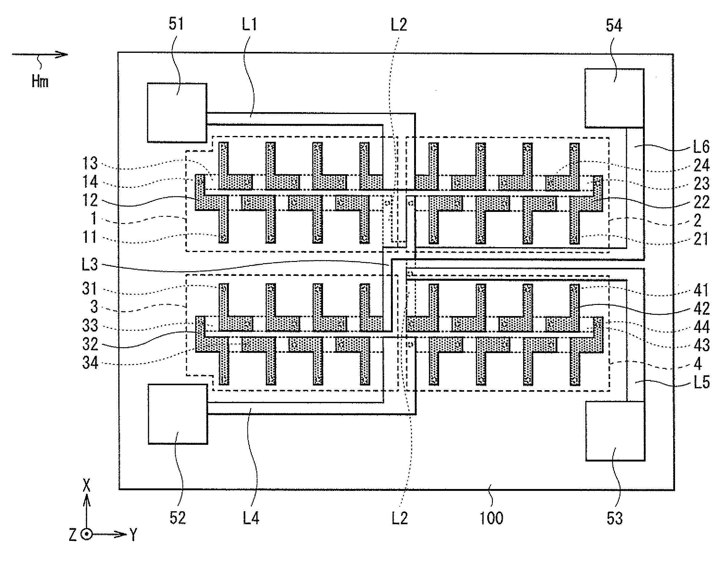
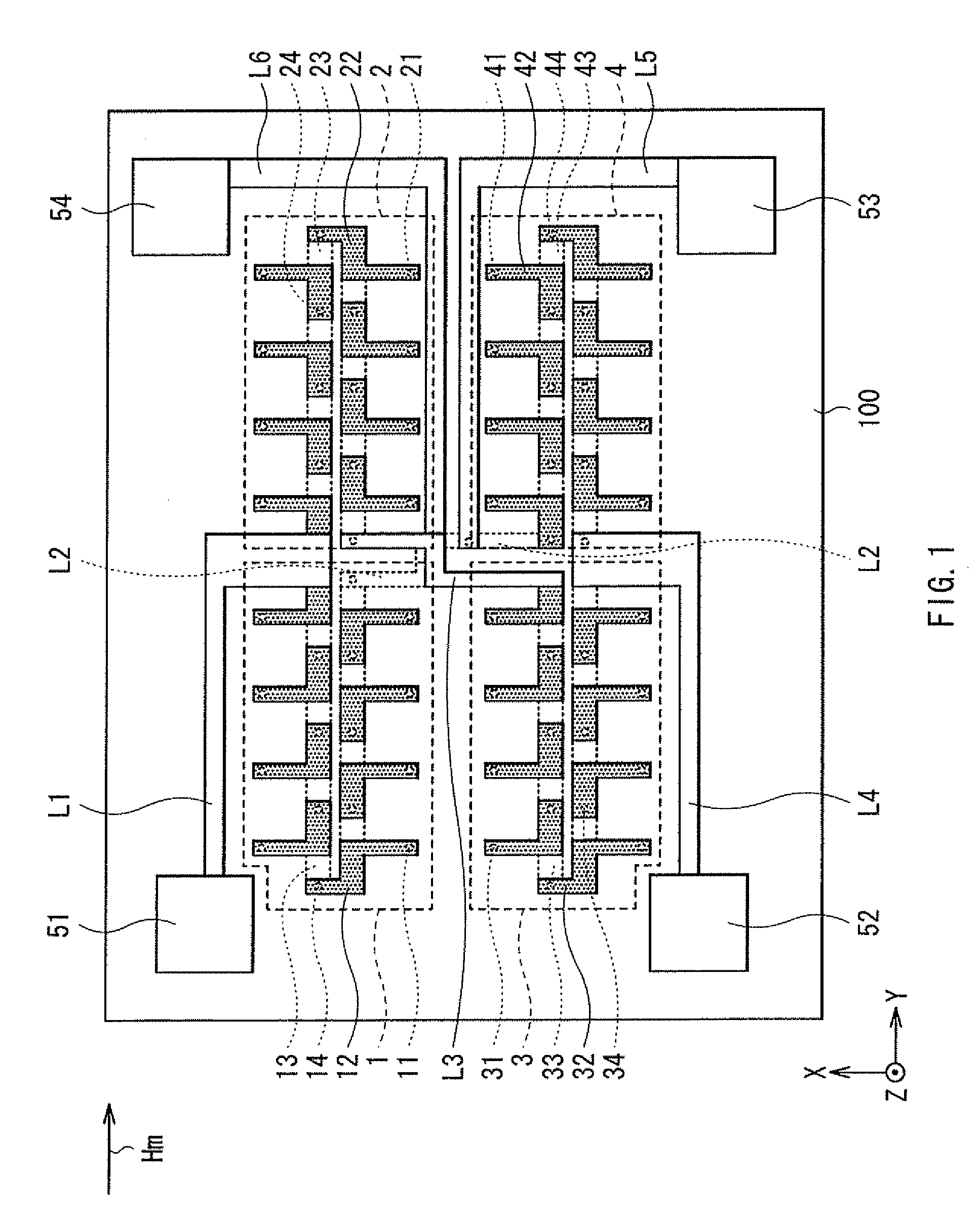
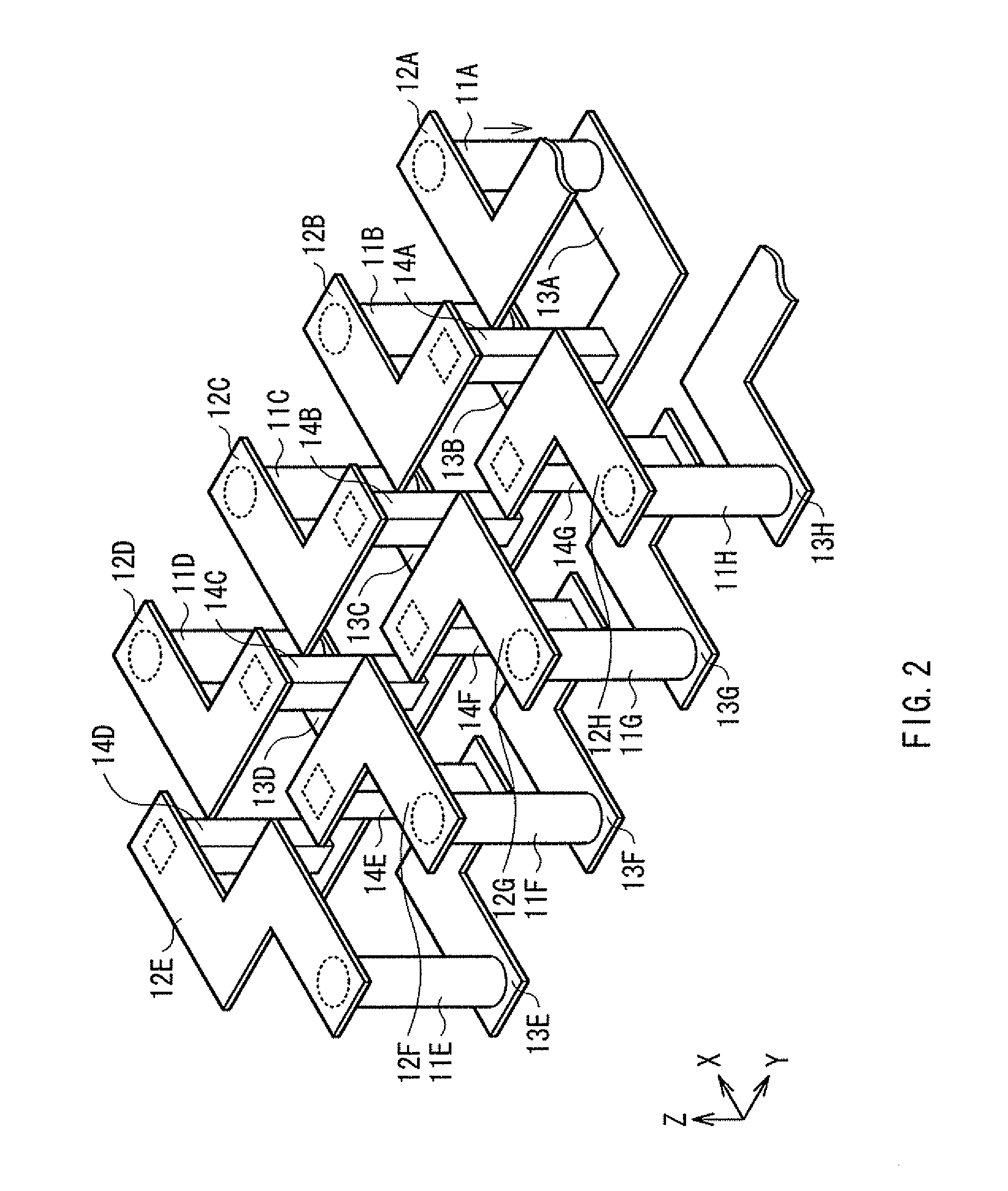
[0036]First, a configuration of a magnetic sensor according to one embodiment of the invention will be described with reference to FIGS. 1 to 16B. FIG. 1 is a plan view illustrating an overall configuration of the magnetic sensor according to the embodiment. FIG. 2 is an enlarged perspective view illustrating a main configuration of the magnetic sensor.

[0037]The magnetic sensor according to this embodiment includes first to fourth magnetoresistive (MR: Magneto-Resistive effect) elements 1 to 4 (hereinafter may be simply referred to as “MR elements”), pads 51 to 54, interconnections L1 to L6, and a difference detector AMP (described later), and so forth, which are provided on a substrate 100. The magnetic sensor may detect a magnitude of a signal magnetic field Hm applied in a plus Y direction, for example. More specifically, the magnetic sensor may be used as a c...


PUM

PropertyMeasurementUnit
currentaaaaaaaaaa
temperatureaaaaaaaaaa
magnetoresistiveaaaaaaaaaa

Abstract

A magnetic sensor includes: a first and a second magnetoresistive elements each including: a magnetization free layer; a nonmagnetic spacing layer; a magnetization pinned layer having one or more first layers of a first group of ferromagnetic layers and one or more second layers of a second group of ferromagnetic layers, in which the first layer and the second layer are stacked alternately with a nonmagnetic coupling layer in between, and so antiferromagnetically coupled to each other as to have opposite magnetizations to each other; and an antiferromagnetic layer pinning magnetization orientation in the one or more first and the second layers. The first layers in the first magnetoresistive element are one more in number than that of the one or more second layers. The number of the one or more first layers and that of the one or more second layers in the second magnetoresistive element are equal.

Description

BACKGROUND OF THE INVENTION[0001]1. Field of the Invention[0002]The invention relates to a magnetic sensor capable of detecting a change in a magnetic field highly sensitively, and to a manufacturing method thereof.[0003]2. Description of the Related Art[0004]In general, when accurately detecting a minute control current flowing in a circuit of a control device, a method is used, where resistors are connected in series in the circuit and a voltage drop of the resistors is measured. However, this may cause some adverse effect on a control system, since a load different from that of the control system is applied. Thus, a method which performs indirect measurement by detecting a gradient of a current magnetic field generated by a control current has been used. For example, the indirect measurement method is achieved by winding a measurement line around a toroidal core, and supplying a control current to the measurement line, to detect a magnetic flux generated in a central part of the ...

Claims


Application Information

Patent Timeline
Patent Type & Authority Applications(United States)
IPC IPC(8): G01R33/02B05D3/02B05D5/00
CPCB82Y25/00G01R33/093G01R33/0052
Inventor OHTA, NAOKITERUNUMA, KOICHIMIURA, SATOSHISAKAI, MASANORIYAMAZAKI, HIROSHI
Owner TDK CORPARATION
Why Eureka
Try Eureka