Aircraft Power Management

a technology for power management and aircraft, applied in the field of power management, can solve the problems that the operational capabilities of conventional vehicles and aircraft, including unmanned drones, may remain limited, and achieve the effects of improving the performance of vehicles, increasing speed, and rapid vehicle respons

Active Publication Date: 2011-03-24
AEROVIRONMENT INC
View PDF7 Cites 41 Cited by
  • Summary
  • Abstract
  • Description
  • Claims
  • Application Information

AI Technical Summary

Benefits of technology

[0004]The disclosed system and method may enhance the performance of a vehicle. The vehicle may include an electric power management system that provides rapid vehicle response to throttle requests. In the case of an aircraft, the power management system may employ a power bus that interconnects a power plant, a propeller drive unit (PDU), a battery, avionics, and auxiliary loads. A controller may direct the operation of the power plant, the propeller drive unit, avionics, and auxiliary loads, and may receive feedback from the battery and power bus. In a slow throttle mode, the controller may direct that the power plant supply power to the propeller drive unit and other loads, and maintain the battery on approximately a trickle charge or discharge. In response to small requested changes in propeller drive unit speed, the propeller drive unit may track the output of the power plant as the power generated by the power plant slowly increases or decreases. In a fast throttle mode, such as upon a sudden and large change in requested propeller drive unit speed, the controller may direct that the propeller drive unit quickly increase speed by drawing additional power from the battery in excess of that being generated by the power plant. Subsequently, the controller may direct that the power plant generate a new power level commensurate with the requested propeller drive unit speed and the power being drawn by any auxiliary loads, as well as replenish the battery.
[0006]In another embodiment, an electric power management system for a vehicle may be provided. The electric power management system may include a power plant configured to generate electrical power and to supply a voltage to a power bus, and a battery interconnected with the power plant via the power bus. The battery may be configured to either discharge current to the power bus or draw current from the power bus to charge itself depending upon a level of a bus voltage associated with the power bus. The system may include a propeller drive unit interconnected with both the power plant and the battery via the power bus. The propeller drive unit may be configured to draw power from the power plant and battery via the power bus. A controller may be configured to direct the power management system in a plurality of distinct modes of operation. Each distinct mode of operation may control the propeller drive unit in a different manner. A first distinct mode of operation may be a slow control mode and a second distinct mode of operation may be a fast control mode. In the slow control mode, the controller may direct that changes in the speed of the propeller drive unit track changes in the power being generated by the power plant by directing the propeller drive unit to use only approximately the amount of power being provided to the propeller drive unit from the power plant via the power bus. In the fast control mode, the controller may direct the propeller drive unit to quickly respond to an increase in speed requested of the propeller drive unit by drawing the additional power necessary from the battery to attain the requested speed and in excess of the power being provided to the propeller drive unit by the power plant via the power bus. As a result, the speed of the propeller drive unit is not limited by a level of power being generated by the power plant.

Problems solved by technology

However, operational capabilities of conventional vehicles and aircraft, including unmanned drones, may remain limited.

Method used


Image

  • Aircraft Power Management
  • Aircraft Power Management
  • Aircraft Power Management

Examples


Embodiment Construction

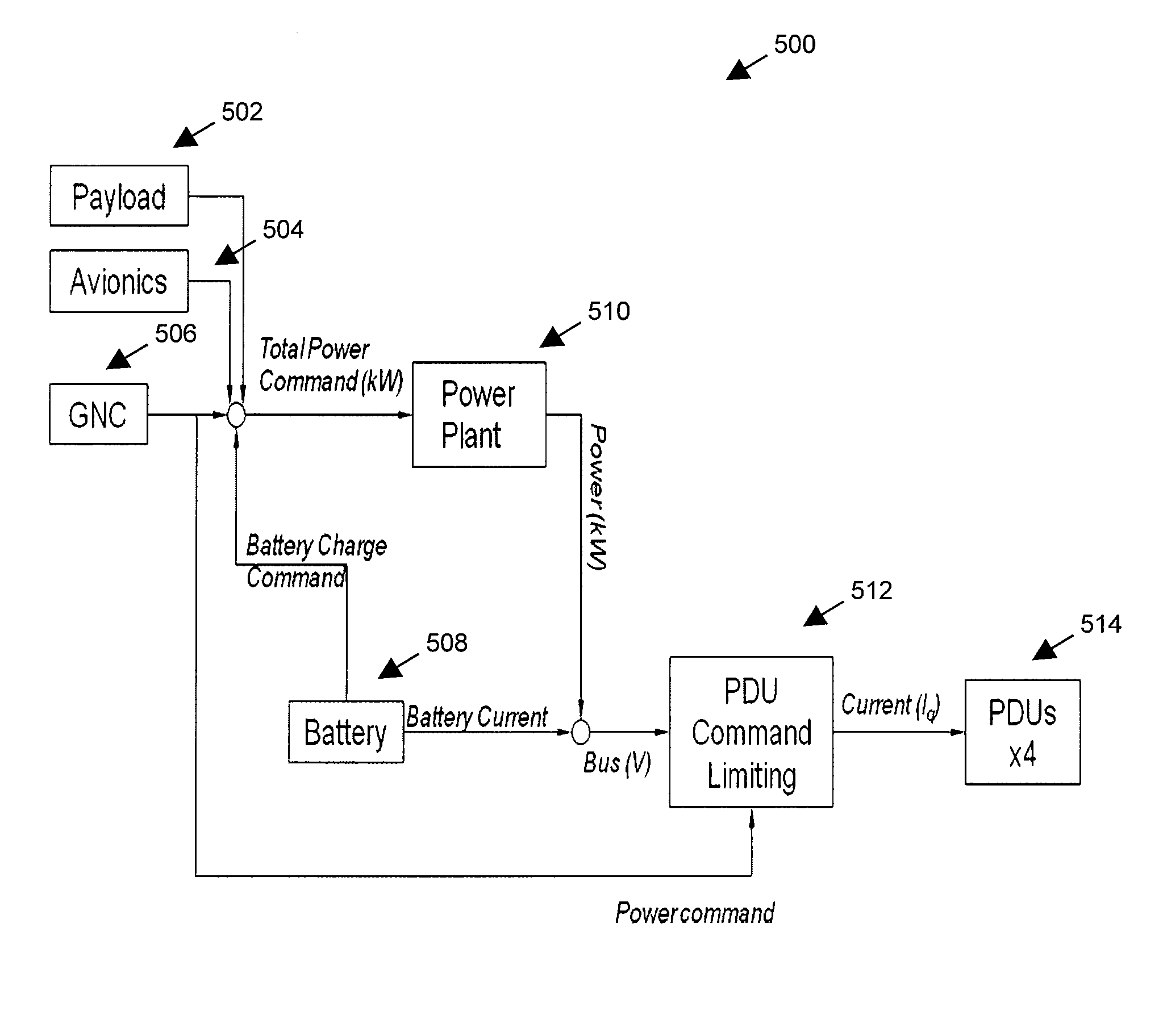
[0022]A system and method may provide an electric power management system that enhances vehicle performance. The electric power management system may increase the response time of a vehicle to significant throttle increases. The vehicle may include a power plant, a battery, and one or more propeller drive units (PDUs) that are interconnected via a power bus. A controller may direct the operation of the power plant and the propeller drive units in multiple control modes. In a slow throttle mode of operation, the propeller drive units may draw power primarily or entirely from the power plant. In a fast mode of operation, the propeller drive units may rapidly draw power from the battery in excess of that currently being provided to the propeller drive unit by the power plant via the power bus.

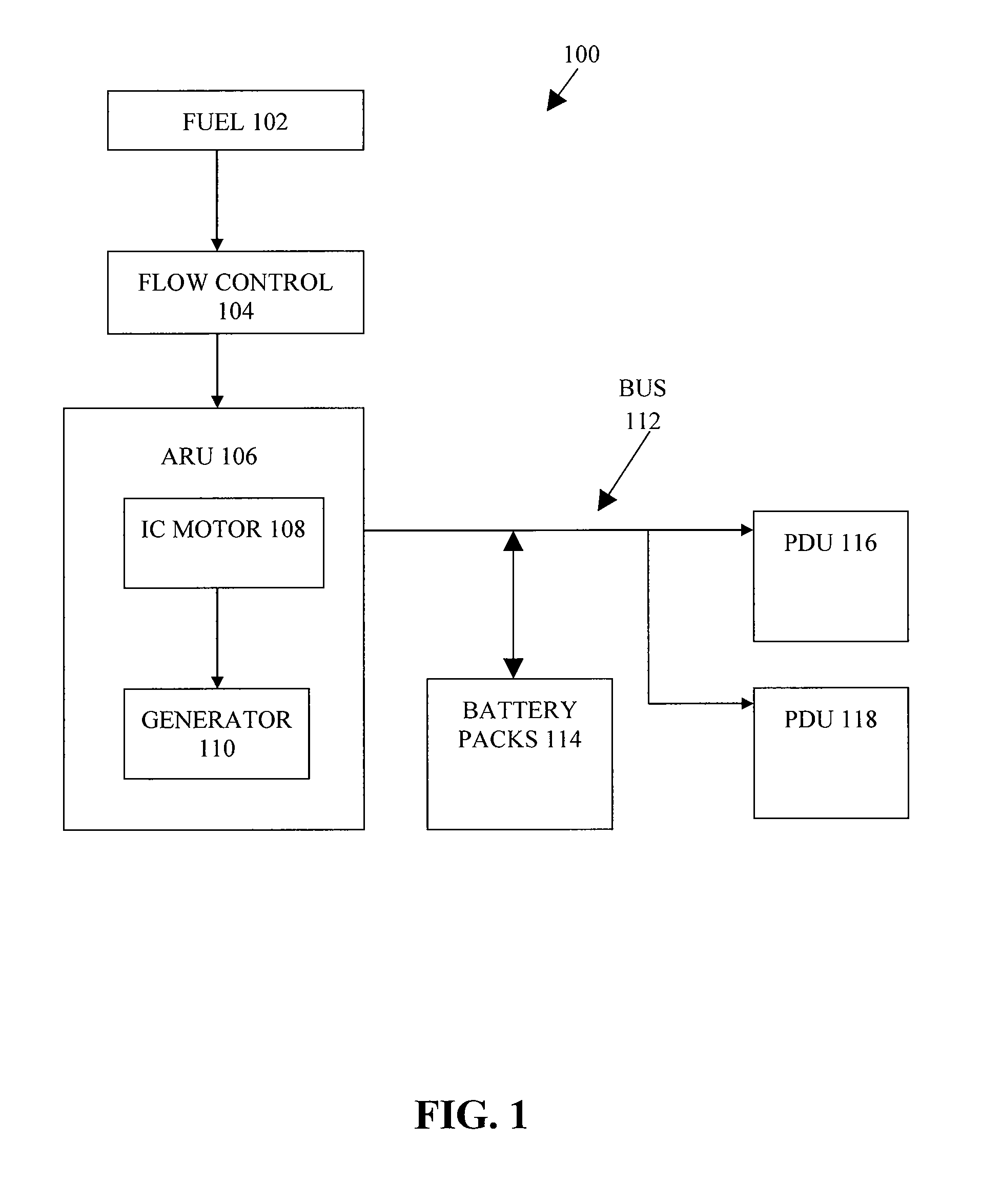
[0023]The power management system may include a power plant configured to generate power and supply a voltage to a power bus. The power plant may include an internal combustion engine, an external...


PUM


Abstract

An electric power management system of a vehicle may interconnect a power plant, a propeller drive unit, and a battery via a bus. A controller may direct the operation of the power plant and the propeller drive unit. In a slow control mode, the propeller drive unit may react slowly to small throttle change requests. In the slow control mode, the propeller drive unit may draw power completely or substantially from the power plant. Upon a throttle request to rapidly change propeller drive unit speed more than a threshold amount, the controller may direct that the propeller drive unit quickly obtain the requested speed by drawing power required from the battery in excess of that being generated from the power plant. Subsequently, the controller may direct that the power plant increase power generation to maintain the propeller drive unit at the new speed, and recharge or float the battery.

Description

FIELD[0001]The present invention relates generally to power management. More particularly, the present invention relates to vehicle electric power management systems.BACKGROUND[0002]The way that the Vietnam War is now remembered as the helicopter war, the current conflicts in Iraq and Afghanistan may be remembered for the use of unmanned drones. Drones may facilitate remote intelligence gathering, alleviating the need for foot soldiers to enter into hostile areas “blind,” with little or no information about the location and strength of hostile forces. Drones may provide close combat support, such as identifying and eliminating targets of interests, alleviating the need to expose soldiers and / or airmen to potential small arms fire, mortars, rocket grenades, road-side bombs, anti-aircraft weaponry, missiles, and other dangers.[0003]With aircraft generally there is a long felt need to enhance performance. Prior power management improvements include those disclosed in U.S. Pat. No. 5,31...

Claims


Application Information

Patent Timeline
Patent Type & Authority Applications(United States)
IPC IPC(8): B64C19/00
CPCB64C39/024B64C2201/042B64D27/24B64D31/02B64D2221/00Y02T10/7258H02J7/1476Y02T50/62Y02T90/44Y02T10/7005H02J7/1446H02J2310/44Y02T10/72Y02T50/60Y02T90/40Y02T10/70B64U50/19B64D41/00
Inventor MATUSZESKI, THADDEUS BENJAMINKOCH, ROLLAND MITCHELLBERMAN, SCOTT GARRETABDULRAHIM, MUJAHID
Owner AEROVIRONMENT INC
Why Eureka
Try Eureka