Concentrated solar thermoelectric power system and numerical design model

a solar thermal and power system technology, applied in the direction of solar heat collectors, lighting and heating equipment, instruments, etc., can solve the problems of destroying the module, not being innovative or original, and removing heat from the cold side of the te module, so as to increase the maximum heat-to-electricity conversion efficiency, the effect of high solar energy-to-electricity conversion efficiency and maximum efficiency

Active Publication Date: 2011-03-31
LADNER DANIEL RAY
View PDF15 Cites 27 Cited by
  • Summary
  • Abstract
  • Description
  • Claims
  • Application Information

AI Technical Summary

Benefits of technology

[0023]The invention described herein, the Concentrated Solar Thermoelectric Power System (herein abbreviated as C-STEPS), is a thermo-optical configuration for the purpose of achieving a high solar energy-to-electricity conversion efficiency based on the Seebeck effect. It does so by implementing concentrated solar energy in a design that combines a single compact dual-function reflector / radiator component with the requirement to operate the thermoelectric (TE) conversion module in an elevated temperature range. By establishing the highest practical TE module hot side (upper) surface temperature Thot by means of solar flux concentration, and the lowest practical TE module cold side (lower) surface temperature Tcold by IR radiation and / or convection or conduction heat removal, the invention generates a large temperature difference ΔT (=Thot−Tcold) across the TE module as a result of the conducted heat flow Qcond. This passive configuration increases the maximum heat-to-electricity conversion efficiency of the TE n- and p-doped device couples that comprise the TE module.
[0024]Values of Thot that exceed a maximum or critical operational value Tcrit, that could cause softening or failure of the TE module components, are avoided by automatically adjusting the TE module cold side surface temperature using a variety of passive or active design mechanisms. These mechanisms in turn regulate Thot to achieve thermal control and maximum efficiency if the solar flux intensity varies. These mechanisms may include but are not limited to the amount of IR radiation emitted from the reflector / radiator surface(s), a heat flow circuit and / or a heat exchanger mechanism to deliver the rejected heat where needed for passive solar heating, a secondary backup convection mechanism, such as a thermostatically driven fan, and a phase change material embedded in or thermally integrated with the reflector / radiator. The reflector / radiator surface(s) may have temperature-dependent IR emissivity properties and the reflector / radiator effective radiator surface area-to- cross-sectional area ratio may vary by baffling the aperture. While the invention provides a method to take advantage of doped bulk alloy semi-conductors, such as doped PbTe, that have very high figures-of-merit and high efficiencies at elevated temperatures, its principle of operation and potential application is not restricted to any particular type of TE device. A Numerical Design Model is used to optimize the C-STEPS geometry and performance and it is a central feature of the invention.

Problems solved by technology

Secondly, the extraction of heat from the cold side of the TE module, whether redirected for passive thermal heating or for heat engine electricity production, or neither, is not an innovative or original concept; it is a necessity for basic operation of any TE module by establishing a temperature difference across the TE module.
Without such heat removal, whether by design or not, the TE module temperature would increase without limit due to its finite heat capacity, resulting in the destruction of the module.

Method used


Image

  • Concentrated solar thermoelectric power system and numerical design model
  • Concentrated solar thermoelectric power system and numerical design model
  • Concentrated solar thermoelectric power system and numerical design model

Examples


Embodiment Construction

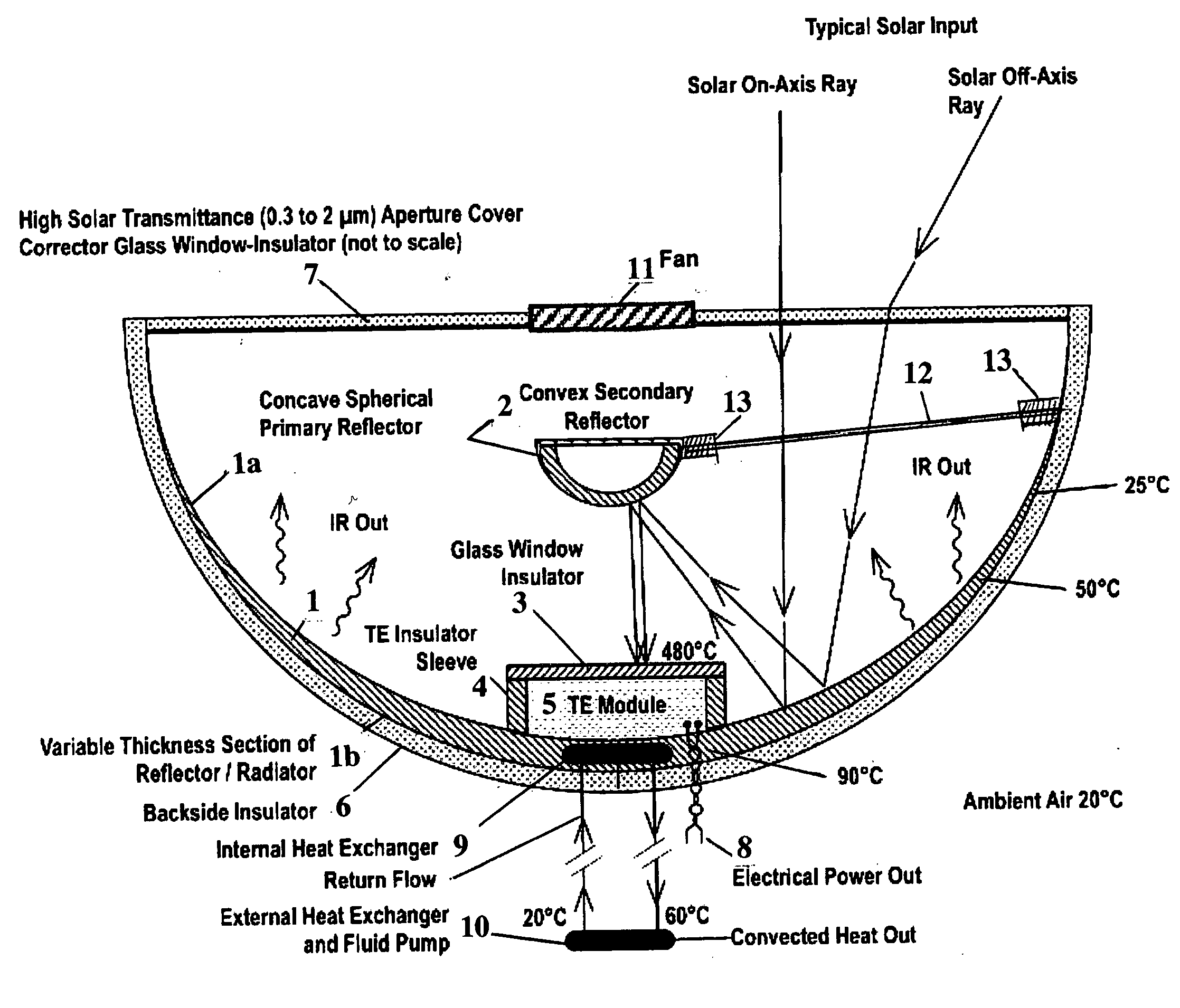
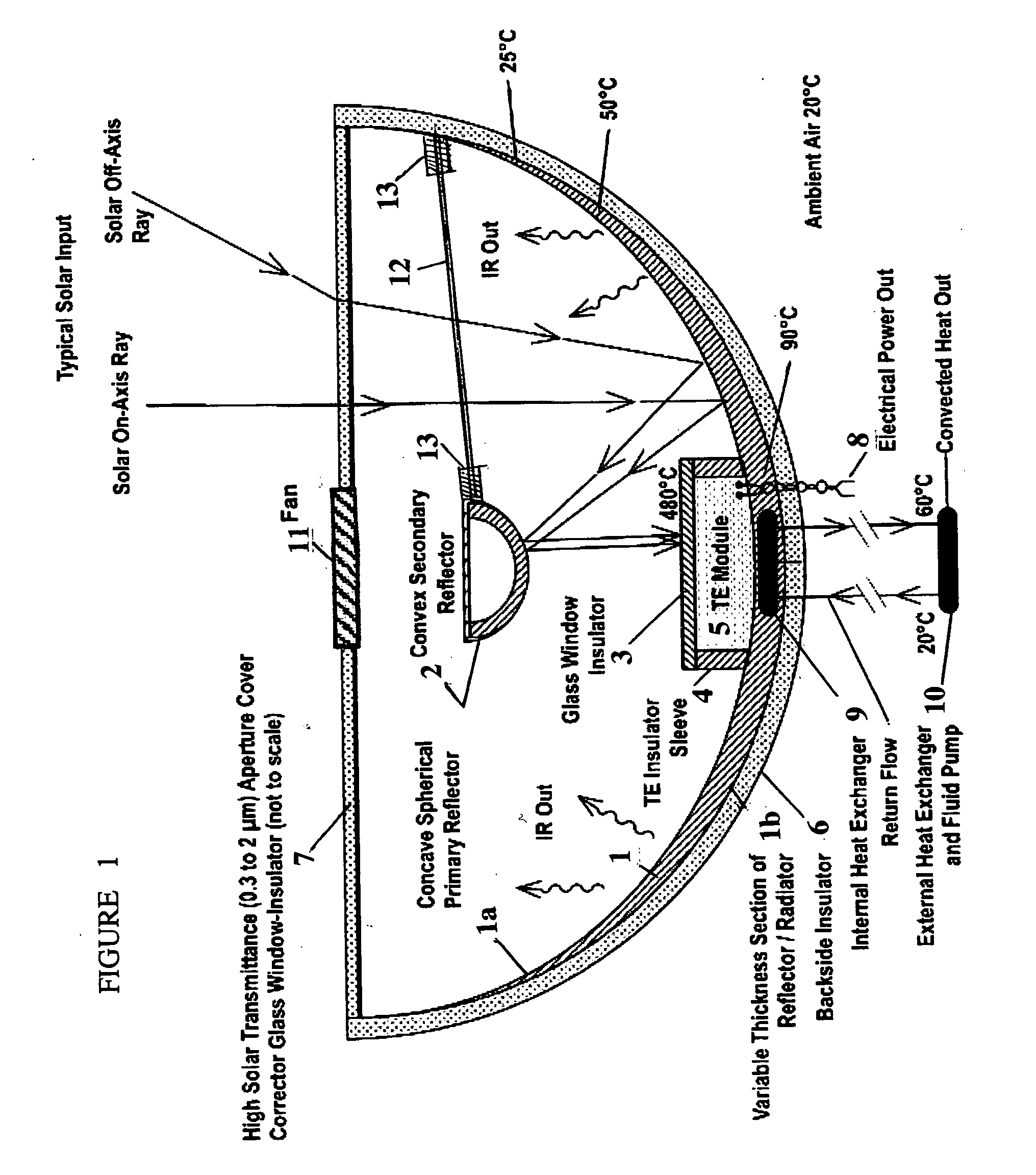
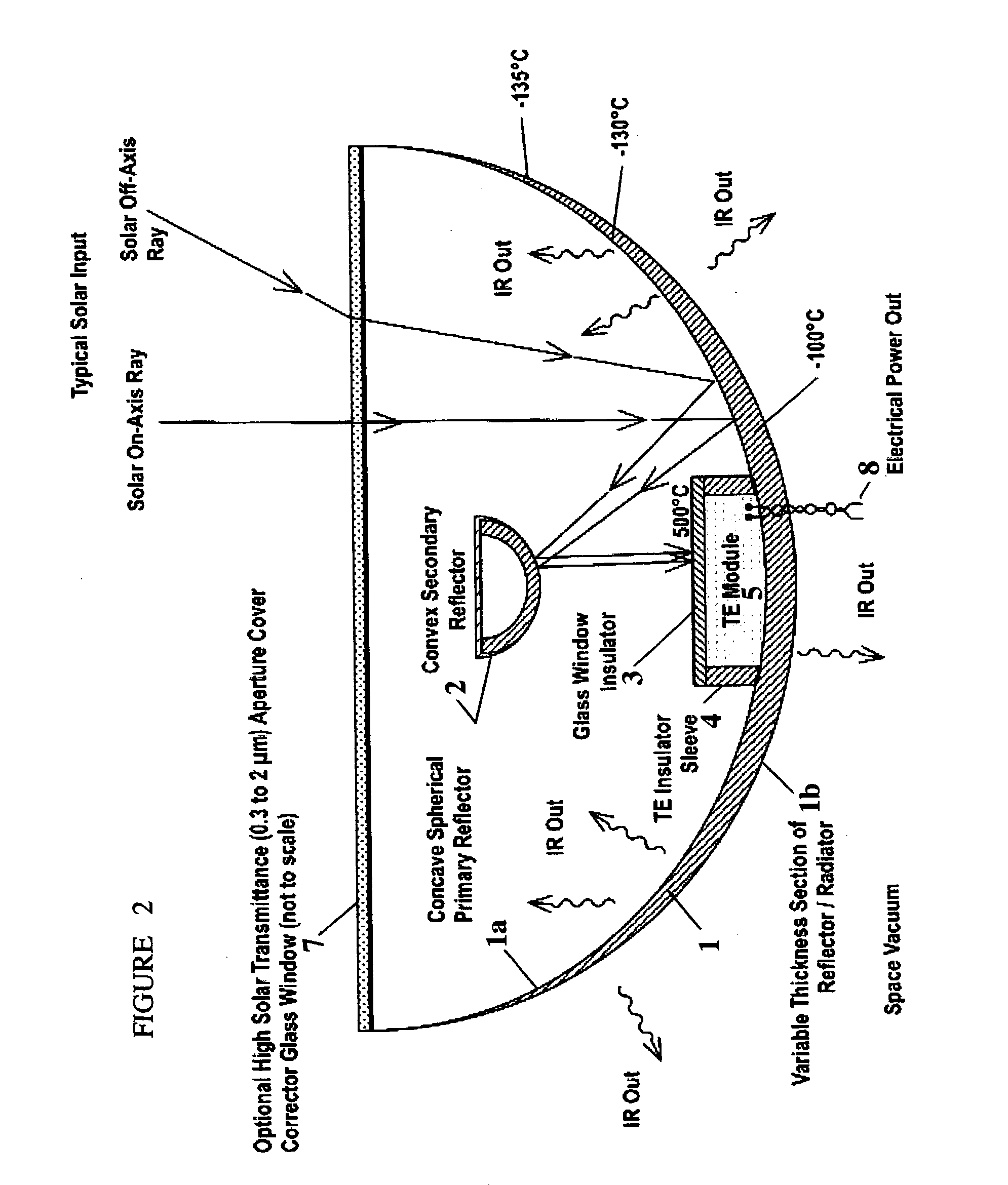
[0031]Thermo-optical Configurations

[0032]The basic design configuration is shown in one embodiment in FIG. 1 and comprises a dual function concave spherical primary reflector 1a / radiator 1b integrated as a single component 1, a convex secondary reflector component 2, and two TE module insulating elements—a glass window insulator 3 and a TE insulator sleeve 4—which are used in conjunction with a TE module 5 consisting of TE semiconductor devices comprising n and p couples. The TE module has a highly absorptive coating in the solar spectrum on its exposed external hot side surface at the window insulator interface for the purpose of converting the concentrated solar energy flux projected onto that surface into an input heat flow Qin. This arrangement effectively creates a high temperature on the hotter side of the TE module, and a large temperature difference ΔT across the module results from heat removal at the TE module cold side. A fraction ηte of the resulting input heat flow prod...


PUM


Abstract

The invention, the Concentrated Solar Thermoelectric Power System, herein abbreviated as C-STEPS, is a thermo-optical system configuration for the purpose of achieving a high solar energy-to-electricity conversion efficiency based on thermoelectric (TE) devices that use the Seebeck effect. It does so by implementing a system for concentrated solar energy using a design that combines a dual-function reflector/radiator component with an active or passive heat convection mechanism to ensure that TE module operation is maintained in a safe elevated temperature range with respect to the ambient temperature. Unsafe module temperatures are avoided by automatically adjusting the TE module hot side temperature directly or indirectly by regulating the TE cold side temperature using a variety of passive or active mechanisms, including the reflector/radiator component, phase change material, or convection/conduction mechanisms. A Numerical Design Model is used to optimize the configuration geometry and performance in various terrestrial and space applications and it is a central feature of the invention.

Description

CROSS-REFERENCE TO RELATED PATENT APPLICATION[0001]The present application claims the benefit of a U.S. Provisional Patent Application Ser. No. US 61 / 277,662, filed Sep. 28, 2009. The entire contents of this provisional patent application are hereby incorporated by reference herein.FIELD OF THE INVENTION[0002]The present invention relates to the conversion of concentrated solar energy into electricity and the utilization of unconverted excess thermal energy for terrestrial water / air heating applications by convection or conduction, as a renewable energy method, and the conversion of concentrated solar energy into electricity and the removal of unconverted excess thermal energy by IR radiation from the primary reflector itself in a space or terrestrial application.BACKGROUND OF THE INVENTION[0003]The basic physical principle of the heat-to-electricity conversion employed by the invention is the Seebeck effect, whereby a temperature difference produces a voltage across a p-n junction....

Claims


Application Information

Patent Timeline
Patent Type & Authority Applications(United States)
IPC IPC(8): H01L35/02G06F17/50F24S23/72F24S23/74F24S23/79
CPCF24J2/13F24J2/14F24J2/18F24J2/4621Y02E10/45F24J2/50F24J2200/04H01L35/30F24J2/4625F24S23/72F24S23/74F24S23/79F24S40/50F24S40/55F24S2201/00F24S80/50F24S80/56Y02E10/40H10N10/13
Inventor LADNER, DANIEL RAY
Owner LADNER DANIEL RAY
Why Eureka
Try Eureka