Cold atom interferometry sensor

a sensor and cold atom technology, applied in the field of can solve the problems of complex and bulky cold atom interferometry sensors of the prior ar

Active Publication Date: 2011-03-31
CENT NAT DE LA RECHERCHE SCI +1
View PDF27 Cites 38 Cited by
  • Summary
  • Abstract
  • Description
  • Claims
  • Application Information

AI Technical Summary

Benefits of technology

[0003]To obtain these two laser beams necessary for Raman pulses, it is possible either to use two distinct laser sources, for example contrapropagative, or to use a single source generating a first dual-frequency laser beam and a reflector arranged to reflect the laser beam so as to generate a second dual-frequency laser beam. This second type of sensor using a single laser source and a reflector for generating the two Raman pulse laser beams has the advantage of having good performance since the relative aberrations between the two Raman beams are reduced. Such an interferometry sensor using a reflector for generating the second Ramon dual-frequency beam is for example described in the application FR-A-2848296.
[0026]This system may also comprise a third interferometry sensor as described previously, the third sensor comprising a third Raman dualfrequency laser, the laser beam generated by the third laser of the third sensor having a propagation direction different from the propagation direction of the laser beam generated by the second laser of the second sensor and from the direction of the laser beam generated by the second laser of the second sensor, the detection means being positioned at the intersection of the propagation directions of the beams generated by the first laser, the second laser and the third laser. In this way, it is possible to establish laser pulse sequences offering access to several inertial quantities successively, in particular in acceleration and in rotation.

Problems solved by technology

Such a cold-atom interferometry sensor therefore has the drawback of requiring at least one Raman laser for the atomic interference measurements, and several lasers for effecting the capture of atoms so as to obtain the cold atoms affording good interferometry measurement.
As a result the cold-atom interferometry sensors of the prior art are complex and bulky.

Method used


Image

  • Cold atom interferometry sensor
  • Cold atom interferometry sensor
  • Cold atom interferometry sensor

Examples


Embodiment Construction

[0034]In the figures, identical references relate, unless indicated to the contrary, to similar technical elements.

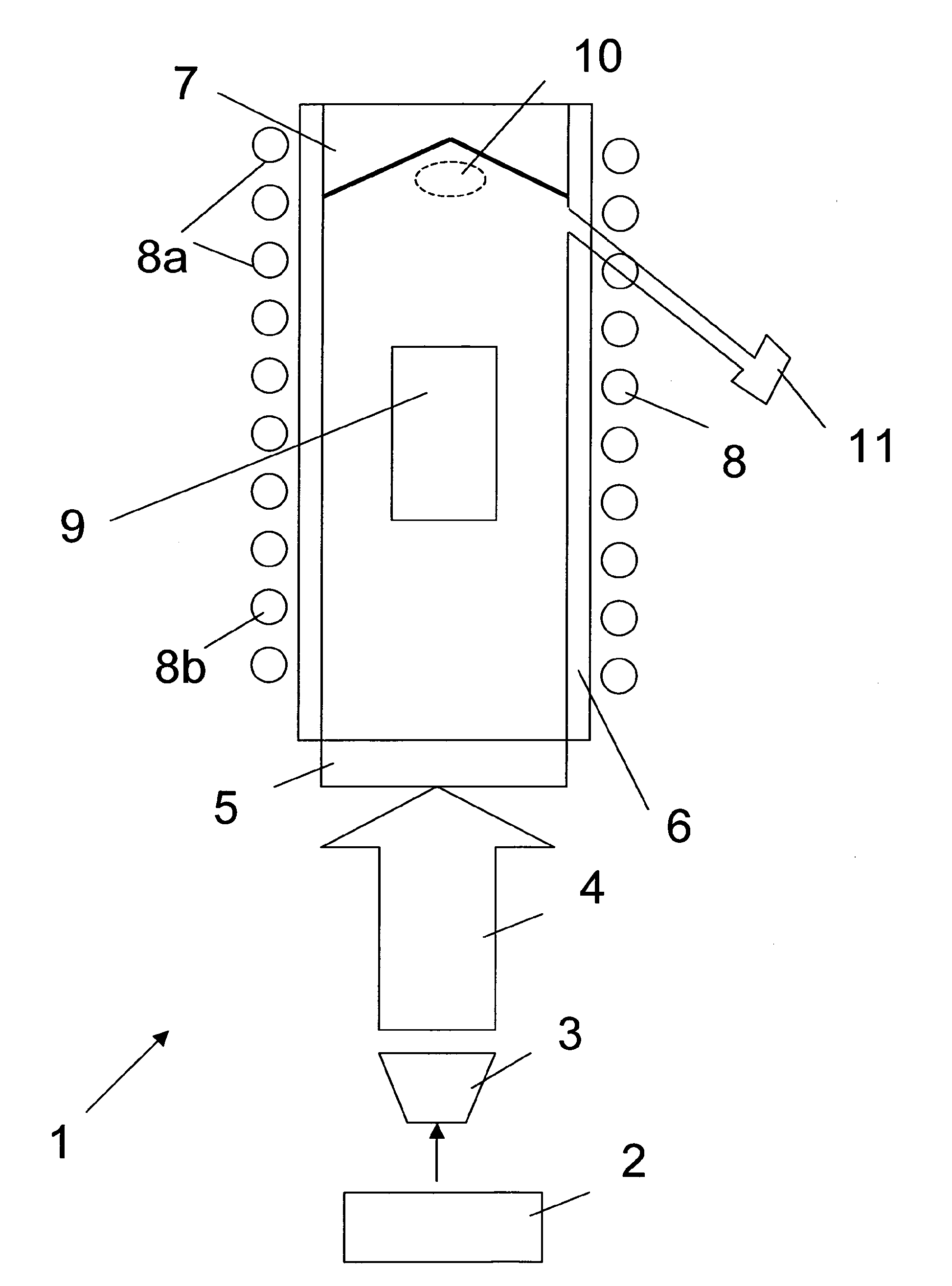
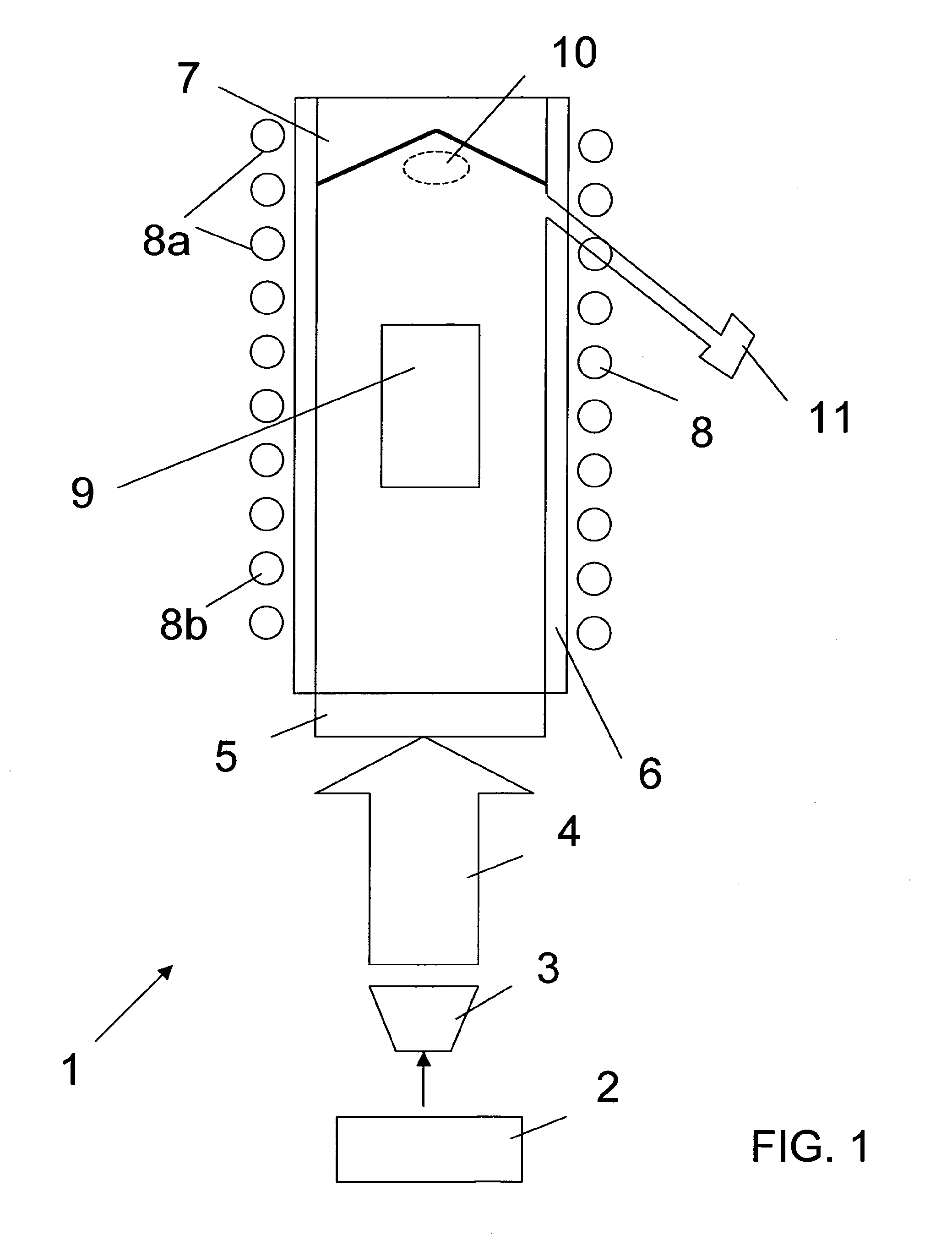
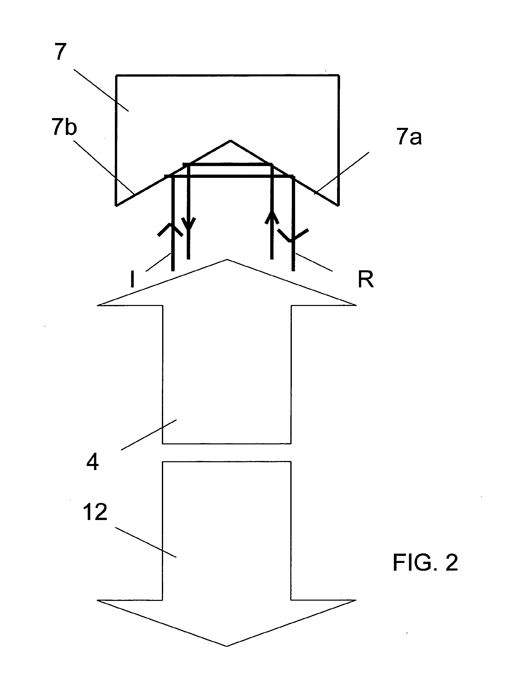
[0035]As illustrated in FIG. 1, an interferometry sensor 1 according to the invention comprises an atom source 11, in the form of a solid reservoir heated and controlled for temperature or a dispenser. The atom source is arranged to make it possible to obtain an atom vapour in a vacuum chamber 6, either by desorption of heat by means of a dispenser, or by light with a technique of the LIAD type, or by controlling the temperature of a cold spot. The vacuum chamber 6 comprises a glass tube the cross section of which may be square or circular. The vacuum chamber 6 is closed at one end by a window 5 and at the other end by a convex reflector 7 that will be described in more detail below. The reflector 7 preferably has a pyramidal shape, the base of the pyramid measuring between one centimeter and five centimetres. In order to reduce the effect of vibration to which the sens...


PUM


Abstract

The disclosure relates to a cold atom interferometry sensor that includes: a source of atoms; a dual-frequency laser capable of generating a first Raman dual-frequency laser beam; a reflector arranged so as to reflect the first Raman dual-frequency laser beam in order to generate a second Raman dual-frequency laser beam, the first laser beam and the second laser beam propagating in different directions in order to obtain atomic interference fringes from the emission of cold atoms obtained from the atom source; characterized in that the reflector is further arranged so as to enable multiple reflections of the first beam on surfaces of the reflector, so that the first beam and the multiple reflections thereof allow the capture of atoms from the atom source in order to obtain the cold atoms.

Description

BACKGROUND AND SUMMARY[0001]The invention relates to a cold-atom interferometry sensor.[0002]The operating principle of such a cold-atom interferometry sensor using stimulated Raman transitions is in particular described in the application U.S. Pat. No. 5,274,232. These cold-atom interferometry sensors are known to have great sensitivity. In such a sensor, it is necessary to obtain two laser beams with different frequencies propagating in different directions in order to obtain atomic interference fringes from the emission of a cooled-atom source.[0003]To obtain these two laser beams necessary for Raman pulses, it is possible either to use two distinct laser sources, for example contrapropagative, or to use a single source generating a first dual-frequency laser beam and a reflector arranged to reflect the laser beam so as to generate a second dual-frequency laser beam. This second type of sensor using a single laser source and a reflector for generating the two Raman pulse laser be...

Claims


Application Information

Patent Timeline
Patent Type & Authority Applications(United States)
IPC IPC(8): H05H3/00G01B9/02
CPCG01C19/58G01P15/00G21K1/006G01V7/00G01P15/006G01P15/08
Inventor BOUYER, PHILIPPELANDRAGIN, ARNAUD
Owner CENT NAT DE LA RECHERCHE SCI
Why Eureka
Try Eureka