

Method of and system for exposing a target
- Summary
- Abstract
- Description
- Claims
- Application Information
AI Technical Summary
Benefits of technology
Problems solved by technology
Method used
Image

Examples
example c
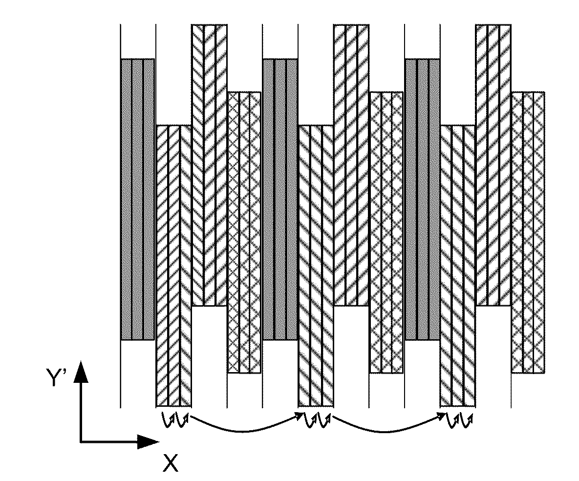
[0142 is a combination of interleaving and stacking. For example D the successive interleaved layers are overlapping like a brick wall. Compared to example C, this configuration will provide better averaging between beamlets. At the stripe boundary there are beamlets that would write over the stripe boundaries.
[0143]FIGS. 12A and 12B schematically illustrate methods of exposing a target by means of a plurality of beamlets in which the exposure pattern is achieved by deflection of each beamlet over the full scan width to be covered by an individual projection lens system. For example, for a field to be exposed with a width of 26 mm using a system having 13,000 projection lens systems, an arrangement of the projection lens systems will result in a full scan width of 2 microns.
[0144]In this example, the target is exposed by using a writing strategy taking into account the projected pitch of the beamlets in the array as projected onto a plane in the X-direction, i.e. Pproj,X. The distan...
PUM
 Abstract
Description
Claims
Application Information