Energy harvester apparatus having improved efficiency

a technology of energy harvester and efficiency, which is applied in the direction of mechanical equipment, generators/motors, machines/engines, etc., can solve the problems of reducing the efficiency of such energy harvesters, and achieve the effect of improving the efficiency of energy conversion

Active Publication Date: 2011-03-31
UNIVERSITY OF LIMERICK +1
View PDF100 Cites 83 Cited by
  • Summary
  • Abstract
  • Description
  • Claims
  • Application Information

AI Technical Summary

Benefits of technology

[0005]We have found a new design for an energy harvester which can show significant improvements in the efficiency of energy conversion. In an embodiment, our harvester includes a housing, an energy supply unit from which energy is accessible to devices outside the housing, and at least one energy transducer coupled to the energy supply unit so as to feed energy to said unit when the transducer is activated.

Problems solved by technology

The effectiveness of such energy harvesters is reduced by various inefficiencies related, for example, to the mechanical coupling between the external energy source and the internal mass elements, and between the internal mass elements and the transducers.

Method used


Image

  • Energy harvester apparatus having improved efficiency
  • Energy harvester apparatus having improved efficiency
  • Energy harvester apparatus having improved efficiency

Examples


examples

Experimental Prototype 1

Coaxial Magnetic Field and Moving Magnet

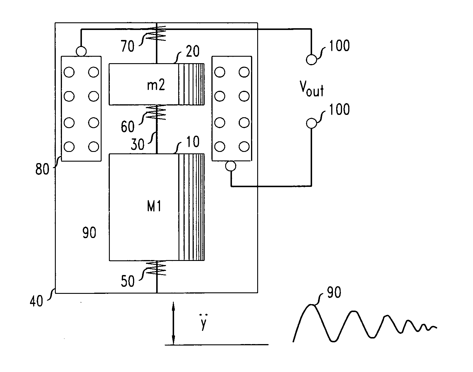
[0075]We constructed a prototype electromagnetic energy harvester dimensioned 50 mm in height and 20 mm in diameter according to a coaxial cylindrical design similar to FIG. 1. We used a lower mass M1 of 47.8 g and an upper mass m2 (including an embedded permanent magnet) of 4.3 g. Thus, the ratio of the respective masses was 11.1.

[0076]The output power PΔt=Vrms2 / RL was measured by averaging the power spectral density of the load voltage signal over a time interval. FIG. 10 shows the power spectrum of the generated voltage across a pure resistive load of RL=200Ω when driven by an input vibration having characteristics of Gaussian white noise. For comparison, the figure also shows the power spectrum of a single-DOF system with the same total mass, volume and acceleration level. More specifically, the upper curve in FIG. 10 is the power spectral density (PSD) of the output voltage across resistive load RL=200Ω, from the v...


PUM


Abstract

An improved vibrational energy harvester includes a housing and at least one energy transducer. In an embodiment, a second mass element is arranged to receive collisionally transferred kinetic energy from a first mass element when the housing is in an effective state of mechanical agitation, resulting in relative motion between the housing and at least one of the second and further mass elements. The energy transducer is arranged to be activated by the resulting relative motion between the housing and at least one of the second and further mass elements. In a further embodiment, kinetic energy is collisionally transferred in a velocity-multiplying arrangement from the first to a second or further mass element that has a range of linear ballistic motion. The energy transducer is arranged to be activated, at least in part, by the ballistic motion of the second or further mass element. The energy transducer, or a portion of it, may be attached to the housing, or it may be attached to another of the mass elements.

Description

FIELD OF THE INVENTION[0001]The invention relates to energy harvesters, and more particularly to devices that convert energy from externally driven mechanical disturbances to electricity or other useful forms.ART BACKGROUND[0002]There has recently been a great deal of interest in harnessing, for useful purposes, some of the mechanical or kinetic energy in the environment that is a by-product of natural or artificial processes. Such energy includes, for example, the vibrations in machines, buildings, bridges, aircrafts, cars, and the human body and the motions of ocean waves. Depending on the nature of the source, their mechanical power spectra range from a few Hz to more than hundreds of kHz. Useful purposes that have been proposed include powering of sensors, as well as providing power for illumination and signal transmission.[0003]Devices that capture mechanical energy from the environment and convert it to useful form are often referred to as “energy harvesters.” In some energy h...

Claims


Application Information

Patent Timeline
Patent Type & Authority Applications(United States)
IPC IPC(8): F03G7/08H02N2/18
CPCH01L41/125H02N2/186H02K35/02H10N35/101
Inventor COTTONE, FRANCESCOGOYAL, SURESHPUNCH, JEFF
Owner UNIVERSITY OF LIMERICK
Why Eureka
Try Eureka