
Piezoelectric MEMS element, voltage control oscillator, communication apparatus, and method of manufacturing piezoelectric drive type MEMS element

a technology of drive type and element, which is applied in the direction of device details, instruments, and piezoelectric/electrostrictive device details, etc., can solve the problems of poor reliability, weak separation force, and contact may become stuck, and achieve simple manufacturing methods and improved production yields. , the effect of simple structur

Active Publication Date: 2011-03-31
FUJIFILM CORP
View PDF12 Cites 35 Cited by
  • Summary
  • Abstract
  • Description
  • Claims
  • Application Information

AI Technical Summary

Benefits of technology

[0009]The present invention has been contrived in view of the circumstances described above, an object thereof being to provide a piezoelectric MEMS element, a voltage control oscillator, a communication apparatus, and a method of manufacturing piezoelectric drive type MEMS element whereby the manufacturing steps are simple, yield can be improved and costs can be curbed.
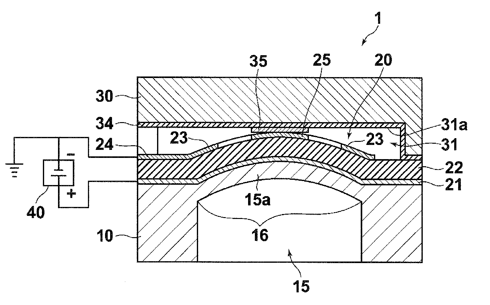
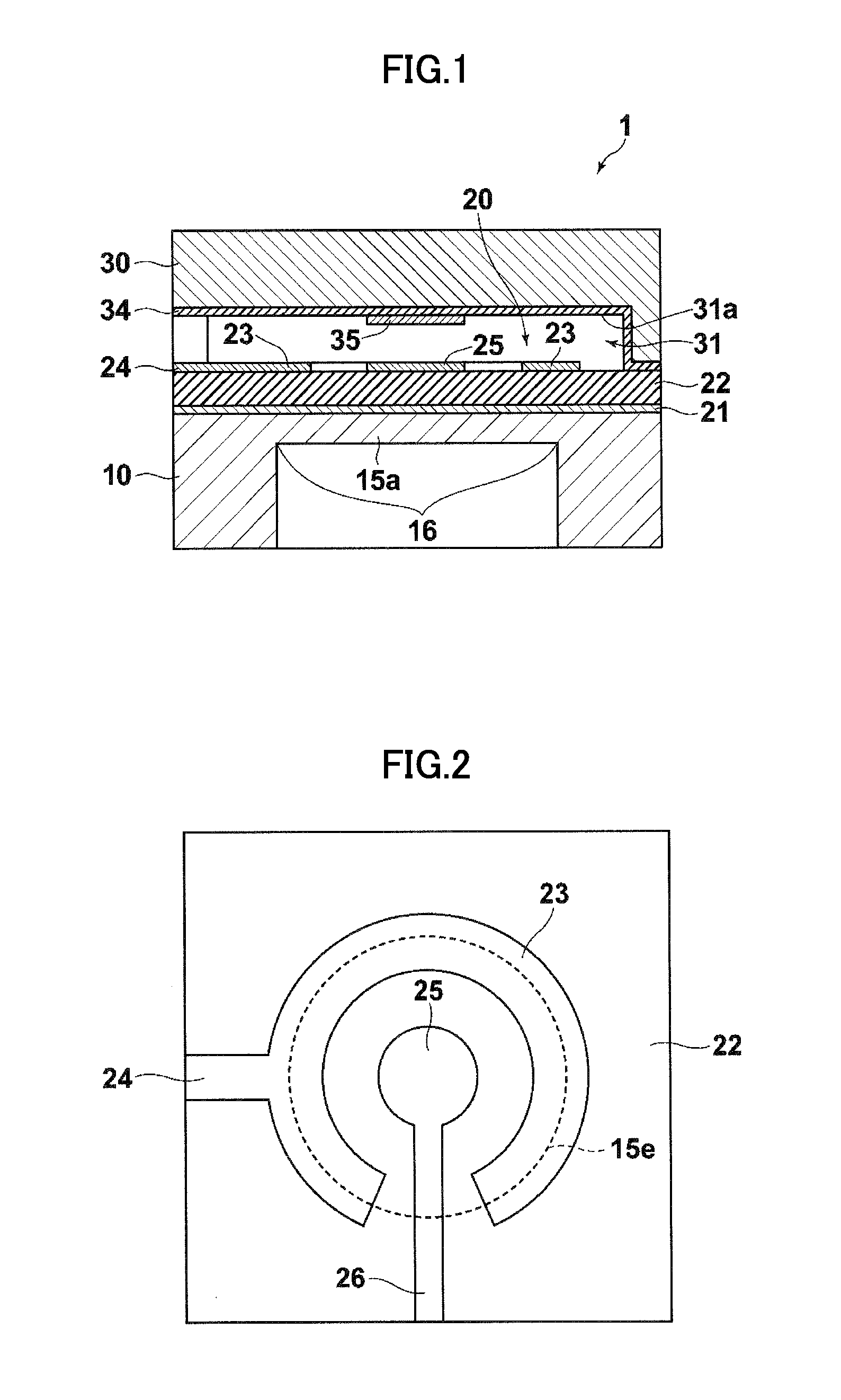
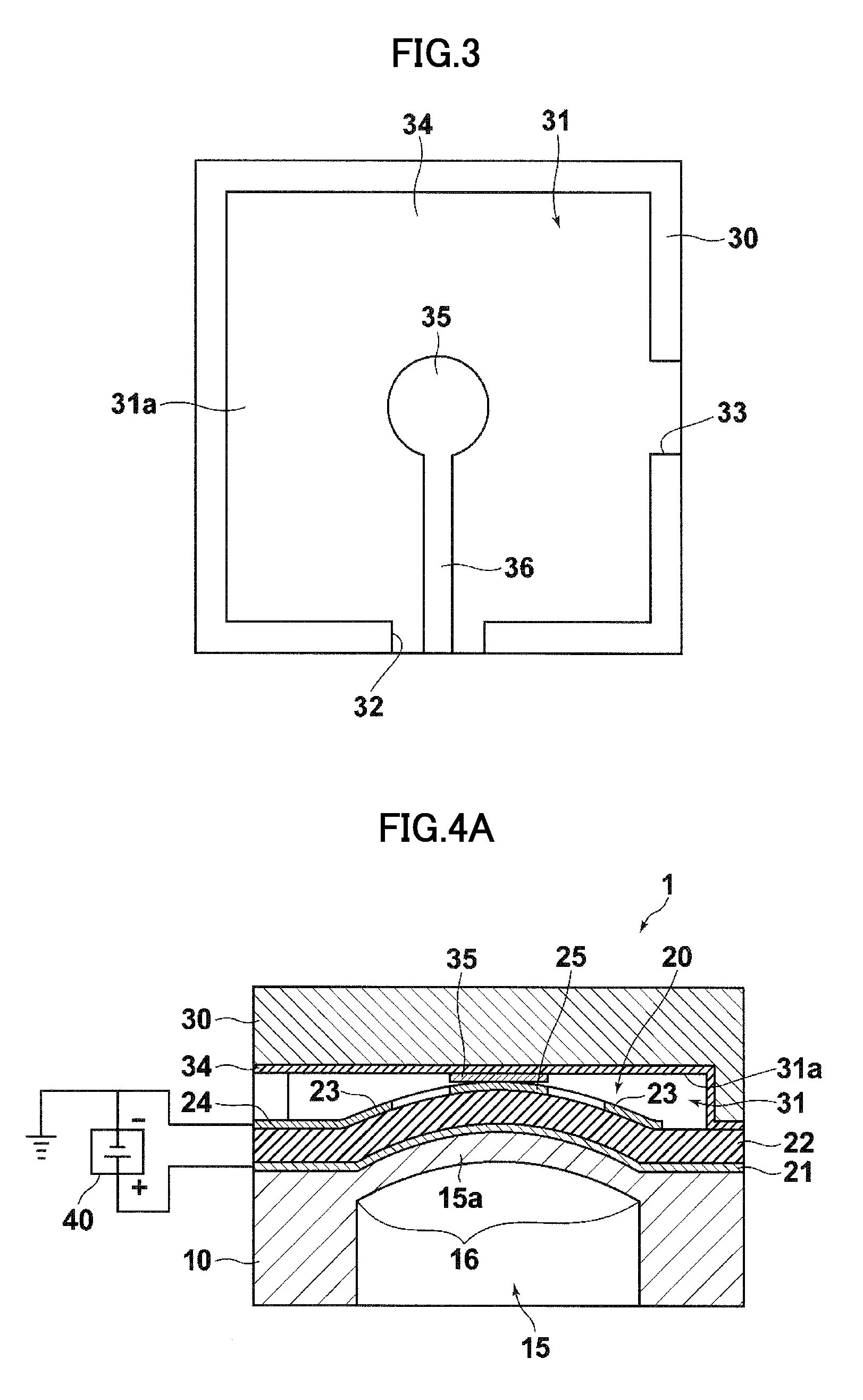
[0027]A piezoelectric drive type MEMS element according to the present invention has a simple structure comprising: a first substrate having, in a portion thereof, a movable part which is driven by a piezoelectric drive section and displaced in a convex shape, a movable electrode being provided on the surface of the movable part; and a second substrate, bonded to the first substrate, which supports a fixed electrode facing the movable electrode via a prescribed gap. Therefore, the manufacturing method for same can be made simple, without having to include steps for fabricating and removing a sacrificial layer, and hence production yield can be improved and manufacturing costs can be suppressed.

Problems solved by technology

When the fixed electrode and the movable electrode make contact with each other, a strong force of attraction is generated, but since their separating action is dependent only on the force of the spring, then the separating force is weak and there is a possibility that the contact may become stuck and reliability is poor.
However, the piezoelectric drive type of MEMS element described in Japanese Patent Application Publication No. 2005-313274 requires a complex process in order to manufacture the beam structure supported at both ends, involving: (i) providing a sacrificial layer on the substrate, (ii) forming a both-end-supported beam structure portion on the sacrificial layer, (iii) creating a cavity by etching from the rear surface of the substrate, and (iv) removing the sacrificial layer, and so on; hence, there are possibilities that it is difficult to raise the yield and lower costs.

Method used


Image

  • Piezoelectric MEMS element, voltage control oscillator, communication apparatus, and method of manufacturing piezoelectric drive type MEMS element
  • Piezoelectric MEMS element, voltage control oscillator, communication apparatus, and method of manufacturing piezoelectric drive type MEMS element
  • Piezoelectric MEMS element, voltage control oscillator, communication apparatus, and method of manufacturing piezoelectric drive type MEMS element

Examples


application example

[0092]Below, an application example of the piezoelectric drive type MEMS element 1 according to the present embodiment will be described briefly.

[0093]FIG. 9 is a circuit diagram of a voltage control oscillator (VCO) 50 in which the piezoelectric drive type MEMS element 1 described above is used as a variable capacitor.

[0094]As shown in FIG. 9, by combining a variable capacitor 54 constituted by the piezoelectric drive type MEMS element 1 with a thin film piezoelectric resonator 53 and an amplifier 55, the capacitor can be used as a voltage control oscillator 50 employed in a movable (mobile) communications apparatus.

[0095]FIG. 10 is a circuit diagram showing the composition of a two-band mobile communications apparatus in which a piezoelectric drive type MEMS element 1 as described above is used as a switch and a variable capacitor.

[0096]This two-band mobile communications apparatus comprises an antenna 71, a tunable matching circuit 72, band switches 73a, 73b, transmission / recepti...


PUM

PropertyMeasurementUnit
Diameteraaaaaaaaaa
Shapeaaaaaaaaaa
Electric potential / voltageaaaaaaaaaa

Abstract

A piezoelectric drive type MEMS element includes: a first substrate including, in a portion thereof, a movable part which is driven by a piezoelectric drive section to be displaced in a convex shape, a movable electrode being provided on a surface of the movable part; and a second substrate which is bonded to the first substrate and supports a fixed electrode facing the movable electrode via a prescribed gap, wherein the piezoelectric drive section includes a piezoelectric film provided on a region of the first substrate which forms the movable part as a portion of the movable part, and a pair of electrodes disposed so as to sandwich the piezoelectric film.

Description

BACKGROUND OF THE INVENTION[0001]1. Field of the Invention[0002]The present invention relates to a piezoelectric drive type Micro Electro Mechanical System (MEMS) element which is used as a switch, a variable capacitor, or the like, and to a voltage control oscillator, a communication apparatus, and a method of manufacturing piezoelectric drive type MEMS element.[0003]2. Description of the Related Art[0004]In recent years, there has been progressive expansion in the range of application of MEMS technology in semiconductor processes. For example, in the field of high-frequency circuits, there are high expectations for the application of this technology to switches and variable capacitors.[0005]An electrostatic drive mechanism employing static electricity has been used principally as the drive mechanism for a conventional MEMS switch or variable capacitor. This is because the material and structure are simple and the process is straightforward. A typical structure is one comprising a ...

Claims


Application Information

Patent Timeline
IPC IPC(8): H01L41/04H01L41/22B81B3/00B81C3/00H01G5/011H01G5/16H01H49/00H01H57/00
CPCH01G5/16H01H57/00Y10T29/42H01L41/0973H01L41/316H01H2057/006H10N30/2047H10N30/076
Inventor HISHINUMA, YOSHIKAZU
Owner FUJIFILM CORP
Learn More