Antenna and communication device

a communication device and antenna technology, applied in the direction of antennas, antenna details, basic electric elements, etc., can solve the problems of varying resonance frequency, and achieve the effect of effective inhibition and stable frequency characteristics

Inactive Publication Date: 2011-03-31
TDK CORPARATION
View PDF7 Cites 1 Cited by
  • Summary
  • Abstract
  • Description
  • Claims
  • Application Information

AI Technical Summary

Benefits of technology

[0012]Preferably, the mark is a recess formed in the outer surface of the dielectric substrate. In this case, the recess has a relative permittivity ∈r of air, so that in the vicinity of the mark, an effective relative permittivity ∈e, which is determined by the relative permittivity ∈r of air and a relative permittivity ∈1 of the dielectric substrate, acts on the antenna electrode. Since the effective relative permittivity ∈e is, of course, lower than the relative permittivity ∈1 of the dielectric substrate, the frequency characteristics can be effectively inhibited from varying with change in mounting position of the antenna electrode.
[0013]Moreover, the mark in the form of a recess can be formed by a simple means of just scraping off the outer surface of the dielectric substrate. Furthermore, unlike other marks made of an organic or inorganic material, air will never invite change in relative permittivity due to aging, so that stable frequency characteristics can be maintained.

Problems solved by technology

However, there is a problem that the resonance frequency varies with change in mounting position of the FPC on the dielectric substrate.

Method used


Image

  • Antenna and communication device
  • Antenna and communication device
  • Antenna and communication device

Examples


Embodiment Construction

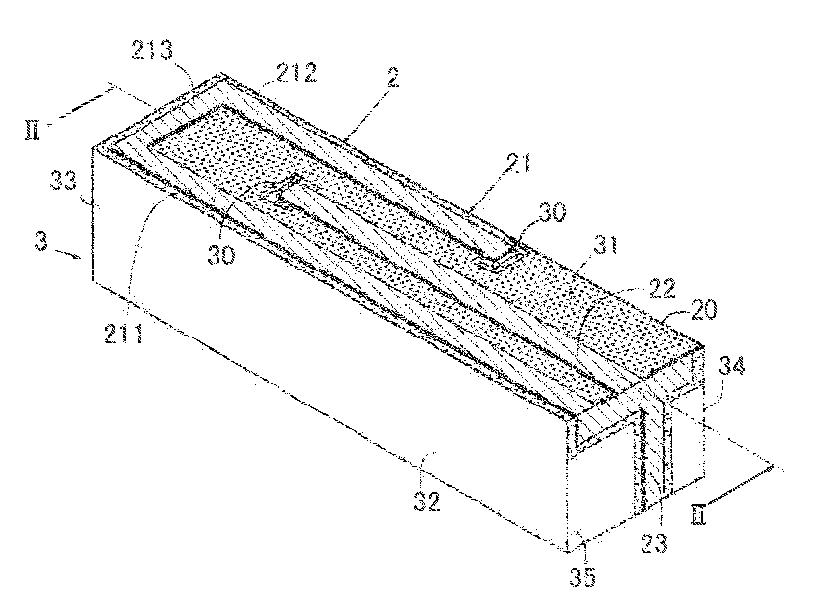
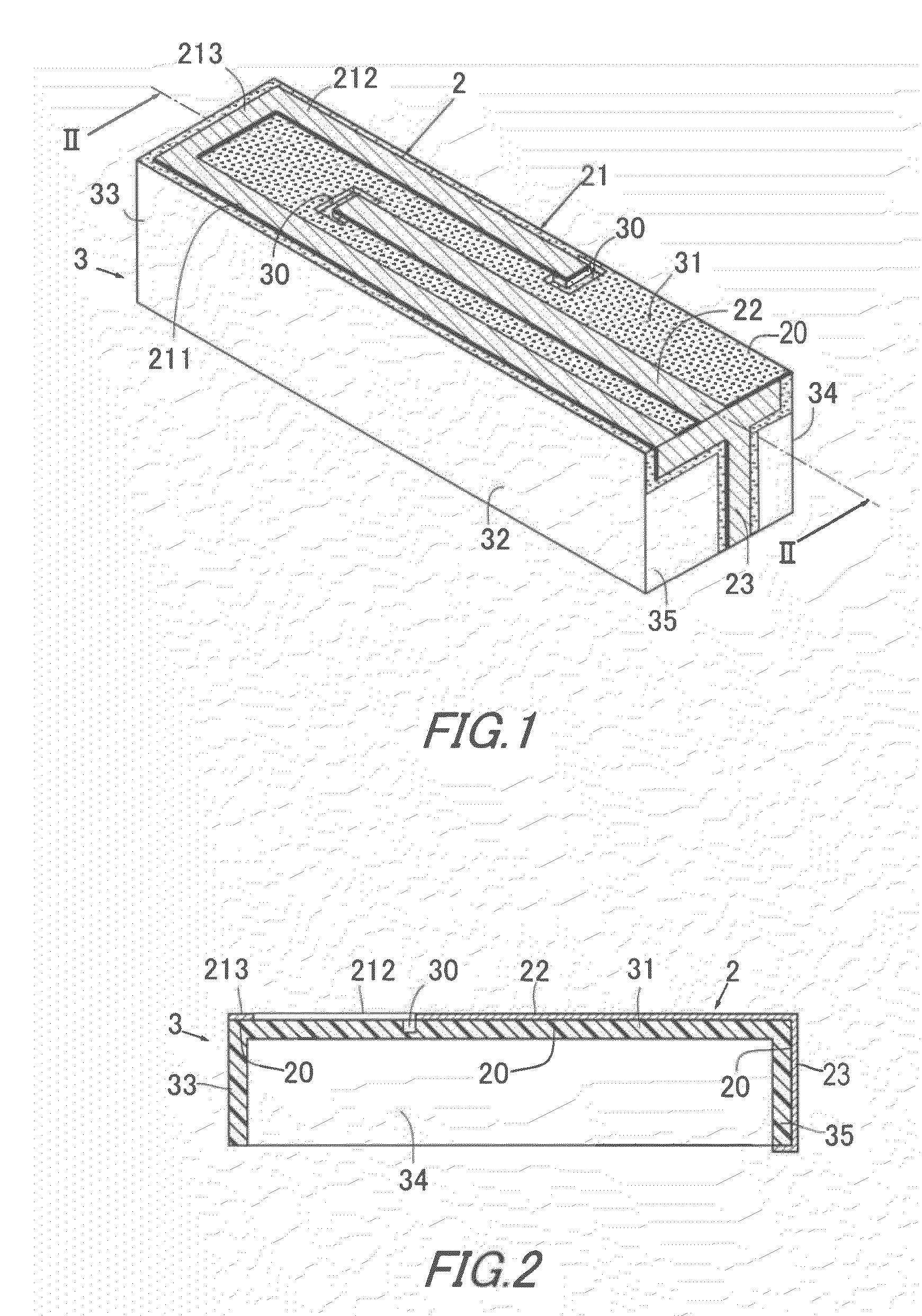
[0037]Referring first to FIGS. 1 and 2, there is illustrated a multiple resonance antenna. The multiple resonance antenna can deal with different two frequency bands even though it is a single chip, and includes an antenna element 2 and a dielectric substrate 3.

[0038]The dielectric substrate 3 is preferably made of a composite dielectric material being a mixture of a synthetic resin and dielectric ceramic powder. For example, the synthetic resin may be ABS (acrylonitrile butadiene styrene) resin or PC (polycarbonate) resin. The dielectric ceramic powder may be titanium oxide series ceramic powder or barium titanate series ceramic powder. Advantageously, the use of such a composite dielectric material makes it possible to adjust the relative permittivity of the dielectric substrate 3, form the dielectric substrate 3 into a required shape by using a molding technique, and color the dielectric substrate 3 by mixing a pigment. The relative permittivity of the dielectric substrate 3 can ...


PUM


Abstract

An antenna includes a dielectric substrate and an antenna element, wherein the dielectric substrate has a mark on an outer surface, the mark having a lower relative permittivity than the dielectric substrate, the antenna element is formed from a FPC film, and the FPC film has an antenna electrode on one side and a flexible insulating film with an adhesive layer on the other side and is adhered to the outer surface of the dielectric substrate with a tip or bend of the antenna electrode aligned with the mark.

Description

BACKGROUND OF THE INVENTION[0001]1. Field of the Invention[0002]The present invention relates to an antenna and a communication device using the same.[0003]2. Description of the Related Art[0004]Antennas are essential for communication devices, and therefore a wide variety of antennas have been proposed and put to practical use. Among them, there is an antenna in which an antenna element formed from a FPC (flexible printed circuits) is employed and the antenna element is adhered to a dielectric substrate using adhesion of the FPC (for example, Japanese Unexamined Patent Application Publication No. 2007-274665).[0005]Since the antenna element is formed from the FPC, an antenna electrode has a high patterning accuracy, thus making it possible to readily manufacture an antenna whose resonance frequency does not vary widely. In addition, since the antenna element can be obtained by simply adhering it to the dielectric substrate, it is easy to manufacture and assemble.[0006]However, ther...

Claims


Application Information

Patent Timeline
Patent Type & Authority Applications(United States)
IPC IPC(8): H01Q1/38H01Q9/04
CPCH01Q1/38H01Q5/371H01Q9/42H01Q9/0421
Inventor SOTOMA, NAOKISHIMODA, HIDEAKITSURU, TOSHIHIRO
Owner TDK CORPARATION
Why Eureka
Try Eureka