Light-driven rotary molecular motors

a rotary molecular motor and light-driven technology, applied in the field of synthetic chemistry, photochemistry, advanced materials, nanometer-scale devices, etc., can solve the problems of complex and degradable fuel sources, limited utility of artificial nanostructure powering in many applications, and lack of precise temporal control of energizing/deenergizing the motor

Inactive Publication Date: 2011-03-31
BOARD OF RGT NEVADA SYST OF HIGHER EDUCATION ON BEHALF OF THE UNIV OF NEVADA RENO
View PDF0 Cites 6 Cited by
  • Summary
  • Abstract
  • Description
  • Claims
  • Application Information

AI Technical Summary

Problems solved by technology

Harnessing biomolecular motors offers the advantages of proven operation and a phenomenal energy efficiency that has been optimized in naturally occurring biological systems.39 However, these motors have a number of characteristics that limit their utility for powering artificial nanostructures in many applications.
Among these are a lack of precise temporal control for energizing/deenergizing the motor, a complex and degradable fuel source, and relatively low speed operation (˜8 Hz for the rotary ATPase motor).
Most restrictive is the narrow range of environmental conditi...

Method used


Image

  • Light-driven rotary molecular motors
  • Light-driven rotary molecular motors
  • Light-driven rotary molecular motors

Examples


example 1

Synthesis of a Preferred Motor I

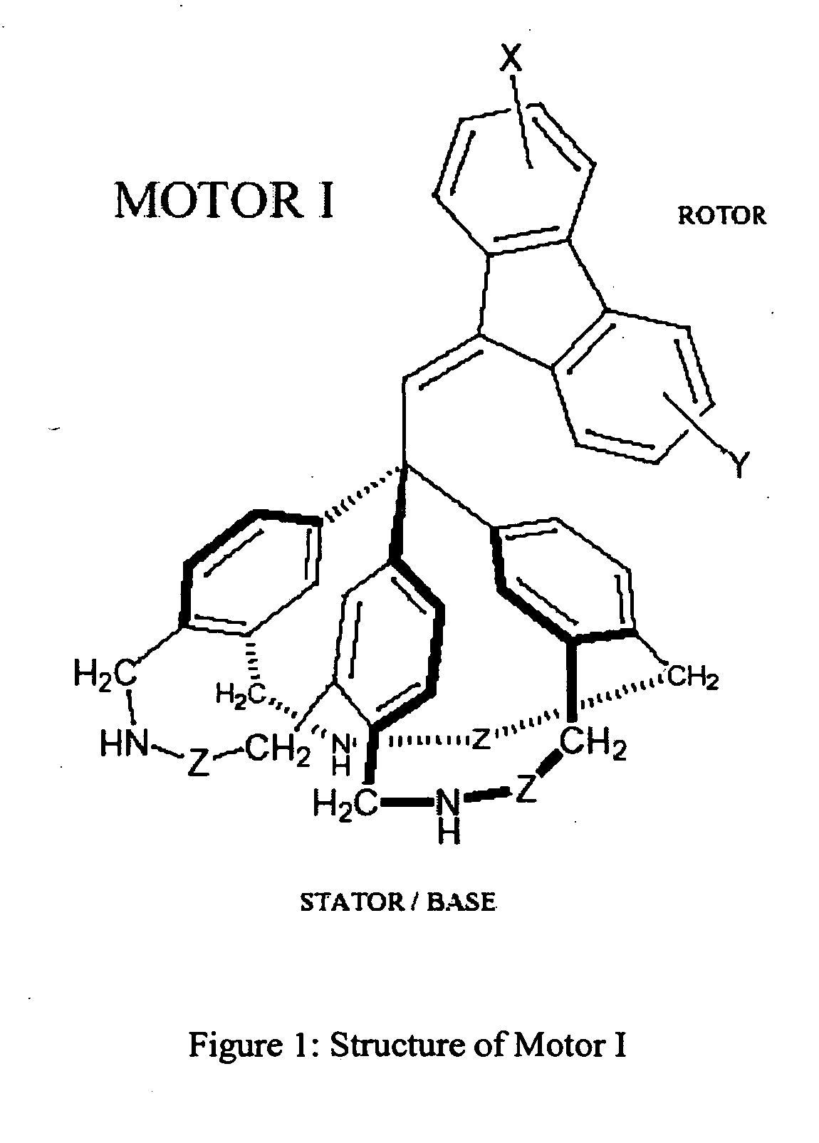
[0099]The stator in a preferred Motor I (see FIG. 1) consists of a triphenylmethane (trityl) group in which the three phenyl rings are linked together by three identical bridges (CH2NHZCH2). These bridges are attached to the phenyl rings in such a manner as to cause each ring to tilt. The resulting stator assembly adopts the shape of a three-bladed propeller. One end of the rotor is inserted into one of the grooves, or clefts, formed by two adjacent tilted phenyl blades.

[0100]The rotor and stator components of Motor I may bear additional substituents or be fused to additional rings so as to produce a stable molecular structure. Some modifications may be useful for the purpose of tuning the physical and chemical properties of the motor. For example, groups X and Y on the rotor may be polar (electron donating or withdrawing) substituents capable of altering the light absorption wavelength, excited state lifetime and twisting efficiency of the chromophor...

example 2

Synthesis of a Preferred Motor I and Fluorene Rotor Derivatives

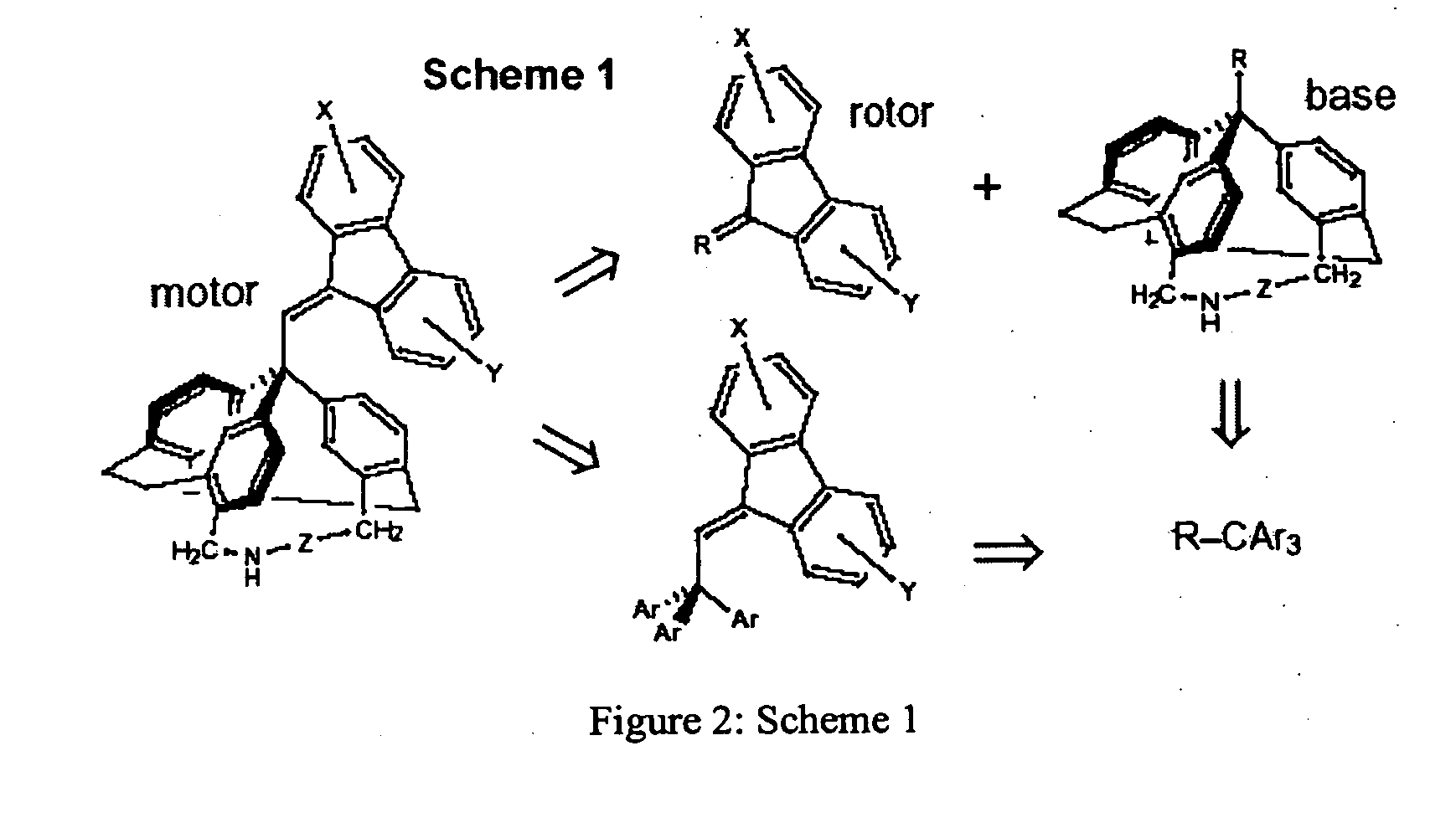
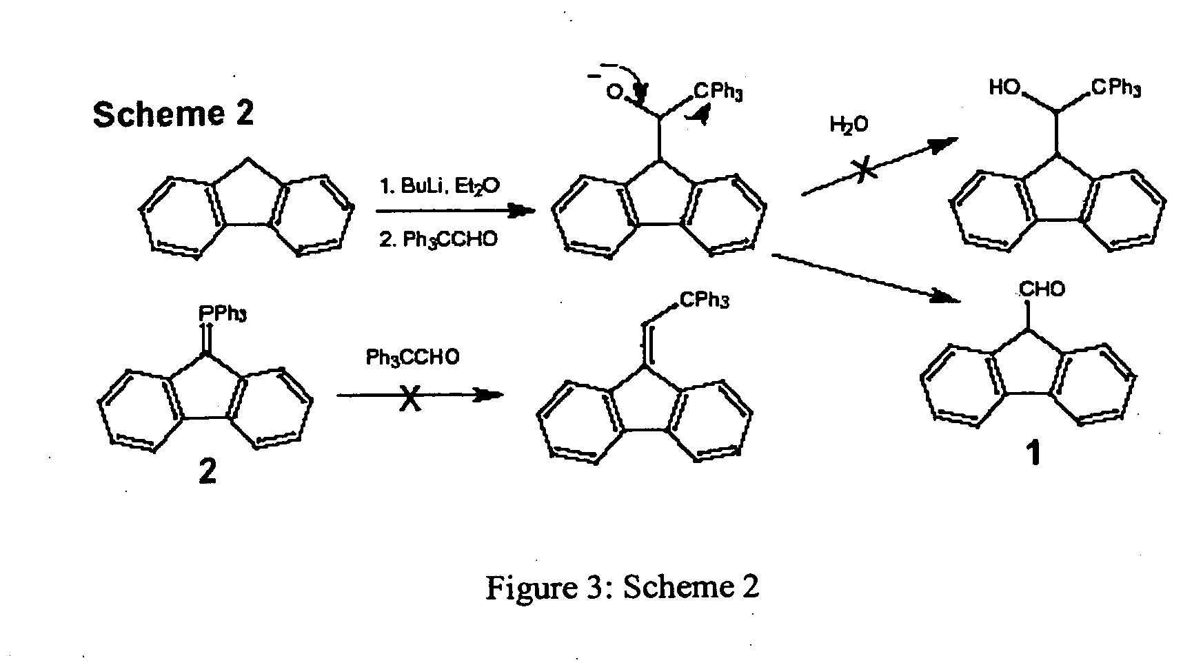
[0112]A preferred compound having the structure of Motor I, (1) consists of an unsubstituted dibenzofulvene unit, and the base (stator) is a triphenylmethane in which the three-fold propeller shape is enforced by bridges containing a nitrogen atom and a C—C triple bond. FIG. 9 shows a retrosynthetic approach, which is based on the synthesis of 9-(2,2,2)-triphenylethylidenefluorene (2).1 A key disconnection corresponds to substitution of bromide in 9-bromomethylene-fluorene (3) with a triarylmethane anion derived from triamine 4. The amino groups may need to be protected as amide or silane derivatives during this substitution reaction and during the synthesis of intermediate 4. These amino groups provide anchor points for immobilizing the final motor on surfaces and incorporating it into DNA. The fluorene rotor will also need to be substituted in order to attach oligonucleotide strands and to tune the photophysical proper...

example 3

Synthesis of a Preferred Motor II

[0120]The molecular architecture of a preferred Motor II (FIG. 19) features a rigid C3-symmetric adamantane base. Three aryl (e.g., phenyl) or alkyl groups shown as R′ in the figure act as the three steric barriers or ridges restricting the rotation of the rotor about the torque angle. The size of this R′ group can be adjusted in order to tune the energy required for rotation of the rotor. The three R groups attached to the base can act as “feet” by anchoring it a surface or another molecule. For this purpose, they can be alkyl chains bearing terminal, reactive functional groups. Alternately, they can be used to adjust the polarity and solubility of the motor molecule. Motor II shares the same dibenzofulvene rotor structure with Motor I. In both cases, the rotor and various substituents can be varied, as described for Motor I.

[0121]Motor II is a desirable, complementary alternative to Motor I for the following reasons: (1) the C3-symmetric adamantane...


PUM

PropertyMeasurementUnit
Structureaaaaaaaaaa
Sizeaaaaaaaaaa
Flexibilityaaaaaaaaaa

Abstract

Compounds of Formula (1) are disclosed.
Cb is a carbocyclic or heterocyclic group having an atom within the cyclic structure selected from C, N, Si, and Cr and singly bound to A. A is CR, COR, CSR, CNR2, CCN, CCONR2, CNO2, CNNAr, CX′, or N. Cr is a chromophore having a substantially planar cyclic structure. The compounds function as nanometer-scale rotary molecular motors powered and controlled by light energy. The design of the molecular motor devices is flexible so that the rotary direction, drive light wavelength, and other physical characteristics can be varied. The compounds can be chemically functionalized to allow it to be integrated into or attached to a variety of structures. The device can be used in applications where mechanical power, positional control, and information encoding are to be generated at the size scale of individual molecules.

Description

CROSS-REFERENCE TO RELATED APPLICATIONS [0001]This application claims priority under 35 U.S.C. §119(e) to U.S. Provisional Application Ser. No. 60 / 407,520, filed Aug. 31, 2003, which is incorporated herein by reference.STATEMENT REGARDING FEDERALLY SPONSORED RESEARCH [0002]This invention was made under a grant from the National Science Foundation (Nanoscale Interdisciplinary Research Team project #021059).FIELD OF INVENTION [0003]This invention relates to the areas of synthetic chemistry, photochemistry, advanced materials, and nanometer-scale devices. Specifically it relates to the construction of controllable molecule-sized synthetic rotary motors.BACKGROUND [0004]Technology at the molecular scale is built on two complementary strategies for manipulating matter and energy. Static nanostructures, exemplified by carbon nanotubes,1-3 metallofullerenes,4-8 dendrimers,9-14 and supramolecular assemblies,15-19 are designed molecular systems that exhibit specific useful properties, includ...

Claims


Application Information

Patent Timeline
IPC IPC(8): C07D487/18C07D493/18C07D495/18C07F7/08C07C35/37
CPCB82Y5/00C07C13/615C07C35/37C07D495/18C07C2103/74C07D487/18C07D493/18C07C2103/18C07C2603/18C07C2603/74
Inventor BELL, THOMAS W.CLINE, JOSEPH I.CREMO, CHRISTINE R.GILLETT, STEPHEN L.FREDERICK, JOHN H.
Owner BOARD OF RGT NEVADA SYST OF HIGHER EDUCATION ON BEHALF OF THE UNIV OF NEVADA RENO
Why Eureka
Try Eureka