Closed-loop load control circuit having a wide output range

a closed-loop load control and output range technology, applied in the direction of electric variable regulation, process and machine control, instruments, etc., can solve the problems of power consumption of 10 w, extensive prior art dealing with led drivers,

Active Publication Date: 2011-04-07
LUTRON TECH CO LLC
View PDF19 Cites 60 Cited by
  • Summary
  • Abstract
  • Description
  • Claims
  • Application Information

AI Technical Summary

Benefits of technology

[0018]According to an embodiment of the present invention, a load control circuit for controlling the amount of power delivered to an electrical load comprises a regulation transistor adapted to be coupled in series with the load, and a feedback circuit coupled in series with the regulation transistor, whereby the load control circuit is able to control the magnitude of a load current conducted through the load from a minimum load current to a maximum load current, which is at least approximately one thousand times larger than the...

Problems solved by technology

The prior art dealing with LED drivers is extensive.
It is also known that LEDs suffer from a phenomena known as “droop” in which the efficiency is reduced as the power is increased.
For example, five LEDs in a first series string each with a forward bias of approximately...

Method used


Image

  • Closed-loop load control circuit having a wide output range
  • Closed-loop load control circuit having a wide output range
  • Closed-loop load control circuit having a wide output range

Examples


first embodiment

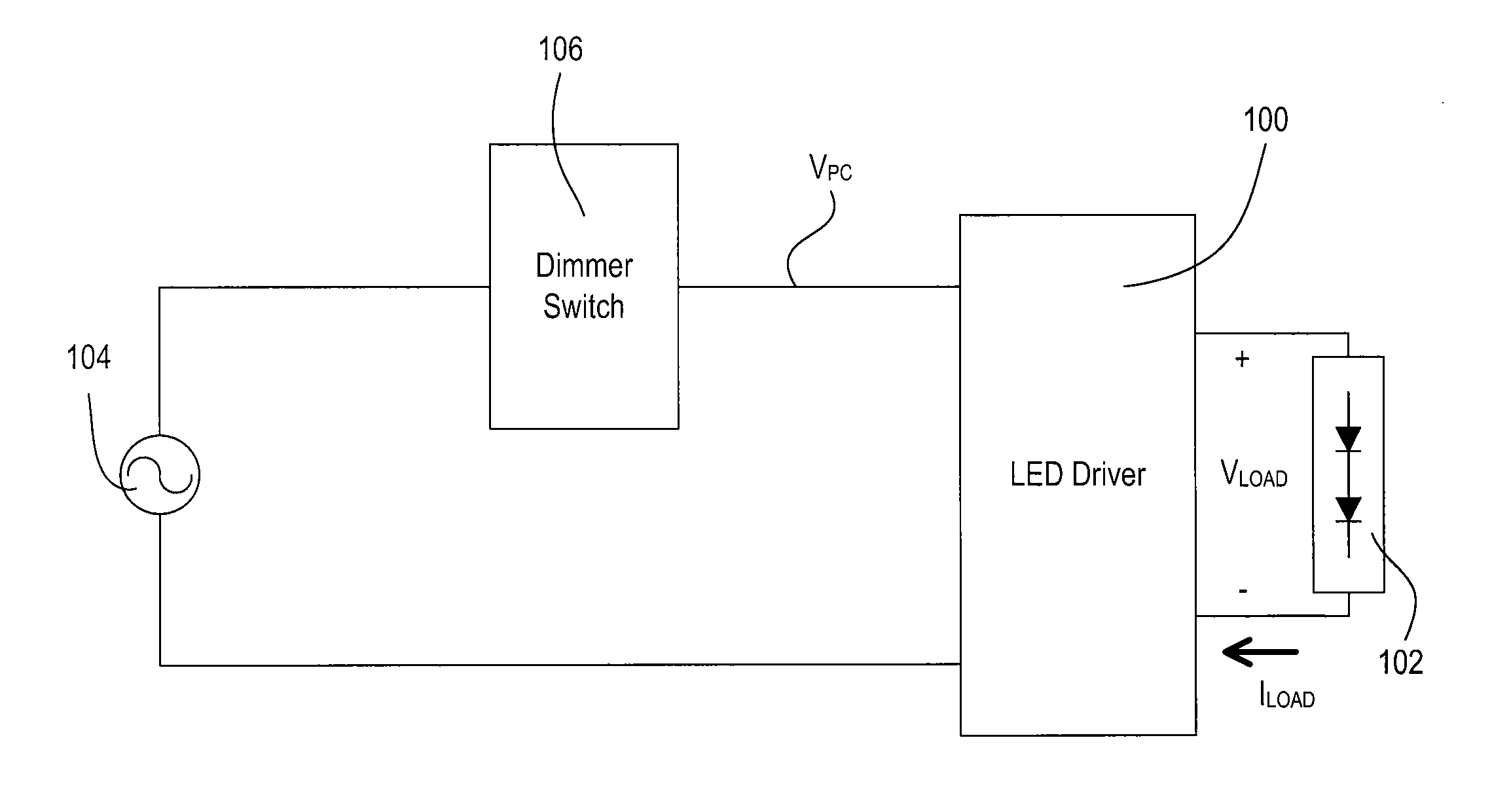
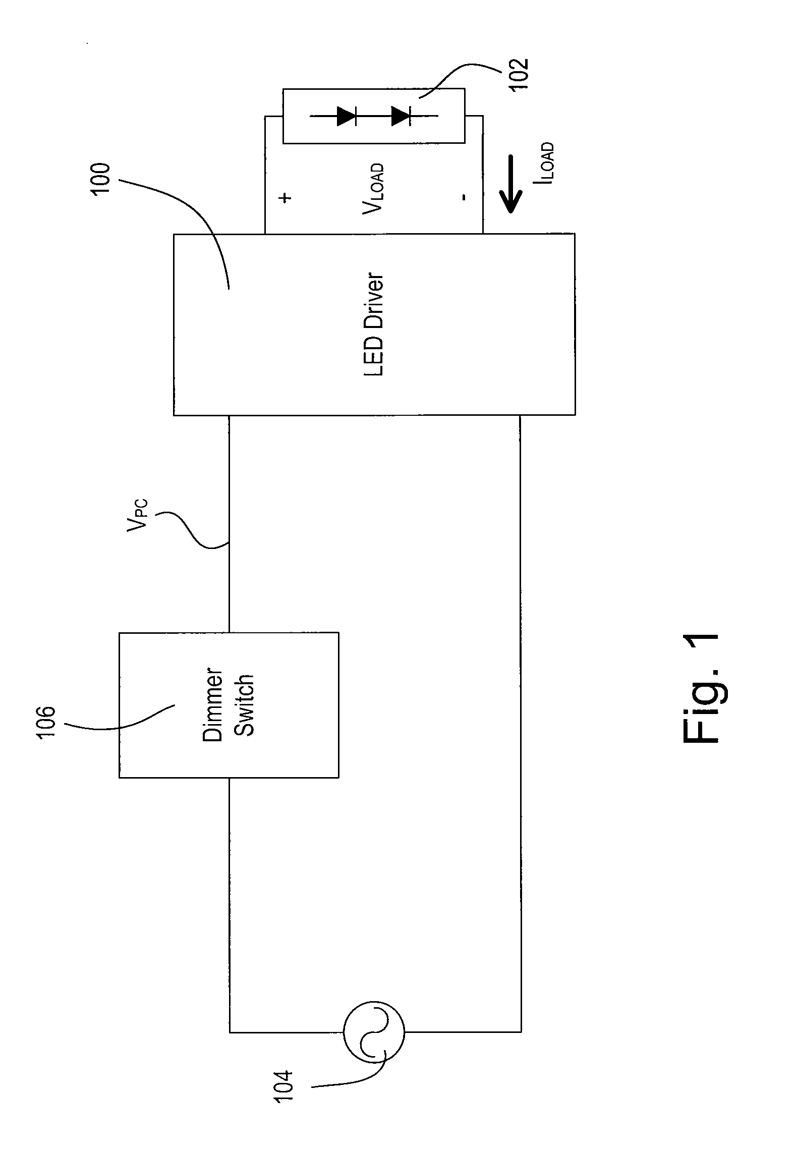
[0051]FIG. 1 is a simplified block diagram of a system including a light-emitting diode (LED) driver 100 for controlling the intensity of an LED light source 102 (e.g., an LED light engine) according to the present invention. The LED light source 102 is shown as a plurality of LEDs connected in series but may comprise a single LED or a plurality of LEDs connected in parallel or a suitable combination thereof, depending on the particular lighting system. In addition, the LED light source 102 may alternatively comprise one or more organic light-emitting diodes (OLEDs). The LED driver 100 is coupled to an alternating-current (AC) power source 104 via a dimmer switch 106. The dimmer switch 106 generates a phase-control signal VPC (e.g., a dimmed-hot voltage), which is provided to the LED driver 100. The dimmer switch 106 comprises a bidirectional semiconductor switch (not shown), such as, for example, a triac or two anti-series-connected field-effect transistors (FETs), coupled in serie...

second embodiment

[0087]According to the present invention, the gain control signal VGAIN is controlled so as to adjust the equivalent resistance RFB of the adjustable gain feedback circuit 770 (to thus increase the gain of the adjustable gain feedback circuit) when the magnitude of the load current ILOAD is less than or equal to a threshold current ITH (e.g., approximately 100 mA). The magnitude of the load current ILOAD crosses the threshold current ITH in the middle of the dimming range of the LED driver 700. When the magnitude of the load current ILOAD is less than or equal to the threshold current ITH, the gain control signal VGAIN is controlled to be high (i.e., at approximately the third supply voltage VCC3), such that the FET Q776 is rendered conductive and the gate of the FET Q775 is pulled down towards circuit common. Accordingly, the FET Q775 is rendered non-conductive, and both the first and second feedback resistors R772, R774 (i.e., approximately 2Ω total resistance) is coupled in serie...

third embodiment

[0097]FIG. 11 is a simplified circuit diagram of the flyback converter 920 of the LED driver 900 of the present invention. The flyback converter 920 comprises a flyback transformer 910 having a primary winding coupled in series with a FET Q912 and a feedback resistor R926. The secondary winding of the flyback transformer 910 is coupled to the bus capacitor CBUS via a diode D914. The secondary winding of the flyback transformer 910 comprises a center tap that generates a center tap voltage VTAP having a magnitude proportional to the magnitude of the bus voltage VBUS. The bus voltage feedback signal VBUS-FB is generated by a voltage divider comprising two resistors R916, R918 coupled across the bus capacitor CBUS and is provided to the control circuit 140. The center tap voltage VTAP is used to generate the second supply voltage VCC2 and the third supply voltage VCC3 as will be described in greater detail below.

[0098]The flyback converter 920 comprises a flyback controller 922, which ...


PUM


Abstract

A load control circuit, such as a light-emitting diode (LED) driver, for controlling the amount of power delivered to an electrical load, such as an LED light source, comprises a regulation transistor adapted to be coupled in series with the load, and a feedback circuit coupled in series with the regulation transistor, whereby the load control circuit is able to control the magnitude of a load current conducted through the load from a minimum load current to a maximum load current, which is at least approximately one thousand times larger than the minimum load current. The feedback circuit generates at least one load current feedback signal representative of the magnitude of the load current. The regulation transistor operates in the linear region to control the magnitude of the load current conducted through the load in response to the magnitude of the load current determined from the load current feedback signal.

Description

CROSS REFERENCE TO RELATED APPLICATIONS[0001]This application claims priority from commonly-assigned U.S. Provisional Patent Application No. 61 / 249,477, filed Oct. 7, 2009, entitled LOAD CONTROL DEVICE FOR A LIGHT-EMITTING DIODE LIGHT SOURCE; U.S. Provisional Patent Application No. 61 / 319,530, filed Mar. 31, 2010; entitled LAMP DRIVER CONFIGURATION DEVELOPMENT TOOL; and U.S. Provisional Patent Application No. 61 / 332,983, filed May 10, 2010, entitled LOAD CONTROL DEVICE FOR A LIGHT-EMITTING DIODE LIGHT SOURCE, the entire disclosures of which are hereby incorporated by reference.BACKGROUND OF THE INVENTION[0002]1. Field of the Invention[0003]The present invention relates to a load control device for an electrical load, and more particularly, to an light-emitting diode (LED) driver having a load current feedback circuit that allows the LED driver to have a wide output current range.[0004]2. Description of the Related Art[0005]Light-emitting diode (LED) light sources are often used in p...

Claims


Application Information

Patent Timeline
IPC IPC(8): H05B37/02G05F1/00H05B44/00
CPCH05B33/0815H05B33/0824H05B33/0845H05B37/029Y02B20/346H05B33/0851H05B45/10H05B45/44H05B47/155Y02B20/30H05B45/3725H05B45/12H05B45/18H05B45/385H05B45/397
Inventor SHEARER, THOMAS M.NUHFER, MATTHEW W.CHITTA, VENKATESHIYER, KARTIKHOERTER, NICHOLAS A.TAIPALE, MARK S.
Owner LUTRON TECH CO LLC
Why Eureka
Try Eureka