
Dc-dc converter

a converter and dc technology, applied in the direction of electric variable regulation, process and machine control, instruments, etc., can solve the problem of changing the brightness of the led(s), and achieve the effect of reducing the cost of the system, simplifying the task of the designer, and reducing the heat loss on the chip

Active Publication Date: 2011-04-07
NXP BV
View PDF4 Cites 24 Cited by
  • Summary
  • Abstract
  • Description
  • Claims
  • Application Information

AI Technical Summary

Benefits of technology

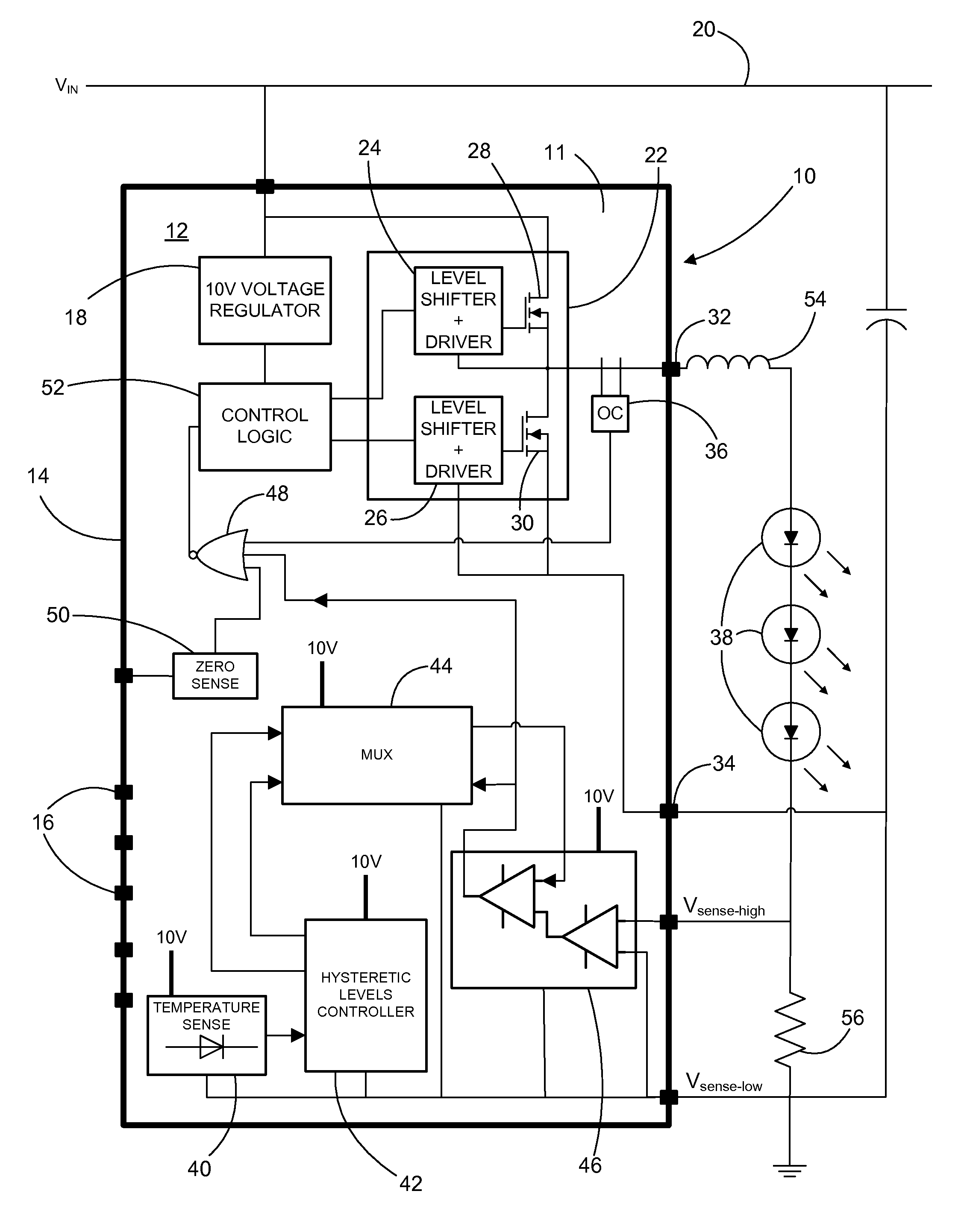
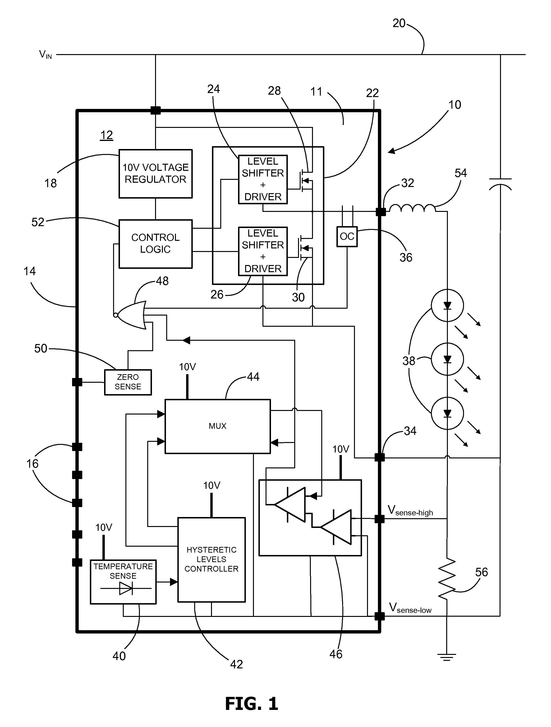
[0012]The present invention is based on the insight by the applicant that a problem usually tackled by DC-DC converter designers (i.e. choosing circuit components to suit a specific application) can be addressed within the integrated circuit itself, thus simplifying the task for the designer. In particular an internal temperature sensing circuit present on an LED driver IC, for example, can be used to anticipate onset of high internal temperature (e.g. the maximum acceptable internal temperature of the integrated circuit) and when that happens, the driver can be configured to de-rate the power dissipated inside the IC and therefore reduce the on-chip heat losses in an attempt to maintain the IC at a safe operating temperature below the shutdown temperature. Furthermore, it has been realised that the de-rating can be achieved substantially without affecting the output from the IC; if the IC is part of an LED driver the visual appearance of the LED(s) is substantially unaffected. In this way an DC-DC converter designer can design for a typical ambient temperature scenario, rather than for the maximum ambient temperature. This enables smaller inductors and heat sinks to be used, reducing the cost of the system. When the worst-case ambient temperature conditions do occur (and when they are approached), the LED driver will automatically de-rate the power dissipated to reduce the heat losses inside the IC.
[0015]Furthermore the inventive concept (to de-rate power dissipation as the IC temperature increases but with little or no effect on perceivable output) can be applied to all manner of integrated circuits. For example a phone charger IC might become hot after a period of use; in accordance with the invention the IC can respond by adjusting some parameter of the IC that affects IC power dissipation in order to reduce on-chip heat dissipation which has least effect on the output to the phone.
[0016]Preferably, said switch-mode power circuit is for supplying a substantially constant average current to said one or more LED, wherein said converter comprises a circuit for controlling said switch-mode power circuit so as to adjust said consumed power whilst leaving said average current substantially unaffected, whereby the visual appearance of said one or more LED appears unaffected. In some embodiments the switch-mode power circuit is integrated in the LED driver IC. When an SMPC is integrated into the IC, the die temperature during use becomes the limiting factor on the die size. By reducing heat losses as the shutdown temperature is approached the die size of the integrated circuit can be reduced.
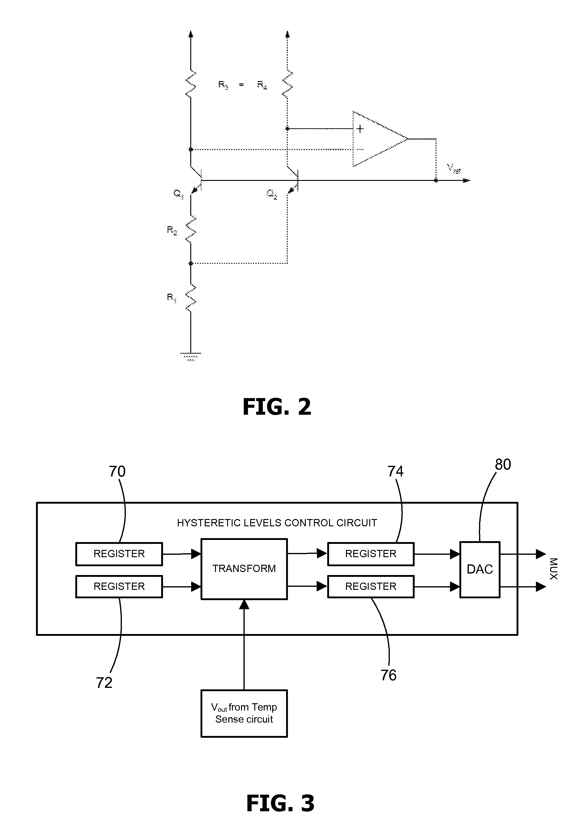
[0021]Preferably, said internal temperature sensing circuit is adapted to supply said output signal to said hysteretic levels controller circuit that is configured to raise said peak voltage level and lower said valley voltage level in response to increasing internal temperature, thereby reducing said switching frequency to effect de-rating of said consumed power.

Problems solved by technology

However, a change in switching frequency can result in a perceived change in brightness of the LED(s).

Method used


Image

  • Dc-dc converter
  • Dc-dc converter
  • Dc-dc converter

Examples


second embodiment

[0064]Referring to FIG. 6 an LED driver 90 according to the present invention is shown in a flyback converter configuration. Such a flyback converter might be useful LED lighting applications with optional dimming control for example. The LED driver 90 is shown connected to a mains supply 91 and comprises a dimmer circuit 92, a damping network 94, a full-wave rectifier circuit 96, a damping resistor 98, a bleeder transistor 100, a controller IC 102, a transformer 104 and one or more LED(s) 106. FIG. 7 shows a particular application employing the LED driver 90, with like numerals indicating like parts.

[0065]In use, rectified AC mains is input voltage to the controller IC 102 which in turn controls the switching of input voltage across the transformer 104. In particular, the controller IC 102 controls the primary side switching by turning on an off an integrated transistor. The LED(s) 106 is connected to the secondary side of the transformer 104, and is therefore isolated from the pri...

third embodiment

[0069]Referring to FIG. 10 an LED driver 120 according to the present invention is shown in a boost converter configuration. Such a boost converter might be useful for LED camera flash applications on mobile telephones for example. The LED driver 120 comprises an internal power supply 122 derived from a battery power supply 124. A switch mode power circuit 126 is controlled by a logic circuit 128 which in the embodiment comprises an I2C interface and control circuit. Two MOSFETs 130, 132 connected to and controlled by the switch mode power circuit 126, in order to apply current through one or two LEDs 134.

[0070]The same control concept as described above in connection with the second embodiment can also be applied to the boost converter. The control is again in the constant frequency and peak current mode. In particular assuming constant Vout, Iout is proportional to Iav*(1−DC)*frequency, where DC is the duty cycle. Therefore de-rating of Ipeak and switching frequency can be adjuste...


PUM


Abstract

A DC-DC converter for driving one or more LED (38), which converter comprises an integrated circuit (12) having a switch mode power circuit (24) and a 5 temperature sensing circuit (40) for providing an output indicating a temperature of said integrated circuit (12), the arrangement being such that, in use, said integrated circuit consumes power, some of which power is dissipated in said integrated circuit as heat causing a rise in said internal temperature, and wherein a change in said output from said temperature sensing circuit (40) is used by said integrated circuit to 10 adjust said consumed power whereby said internal temperature may be controlled

Description

FIELD OF THE INVENTION[0001]The present invention relates to a DC-DC converter for driving one or more LED, to an application specific integrated circuit (ASIC) and an application specific standard product (ASSP) each comprising such a converter.BACKGROUND TO THE INVENTION[0002]A single LED die intended for solid state illumination is generally made from one of two semiconductor materials: InAlGaP (red, orange and amber) and InGaN (green and blue). Similar to standard PN junction diodes, LEDs conduct current when they are forward biased. Two design aspects of LEDs are (1) that they are driven by current, and (2) the forward voltage (VF) is low and DC; typical VF ranges from 2V to 3V for InAlGaP LEDs and from 3V to 4V for InGaN LEDs. The luminous flux of an LED is proportional to the forward current.[0003]Since LEDs are current driven devices, the preferred driving method is with a constant current source; this reduces changes in current due to variations in forward voltage across th...

Claims


Application Information

Patent Timeline
IPC IPC(8): H05B41/36H05B44/00
CPCH05B33/0815Y02B20/346H05B33/0854Y02B20/30H05B45/38H05B45/375H05B45/3725H05B45/385H05B45/18
Inventor DANIEL, BOBBY JACOB
Owner NXP BV
Learn More