Methods of nucleation control in film deposition

Inactive Publication Date: 2011-04-14
STEWART ENGINEERS
View PDF7 Cites 4 Cited by
  • Summary
  • Abstract
  • Description
  • Claims
  • Application Information

AI Technical Summary

Benefits of technology

[0013]The embodiments described herein address some or all of the limitations of film structure control by controlling nucleation. The disclosed embodiments are methods of controlling nucleation of a film, and influencing a subsequent growth of the film, by chemical vapor deposition resulting in an at least partially crystalline film. One method disclosed herein comprises the steps of providing a substrate and depositing an under layer on the substrate in a controlled atmosphere. The under layer h

Problems solved by technology
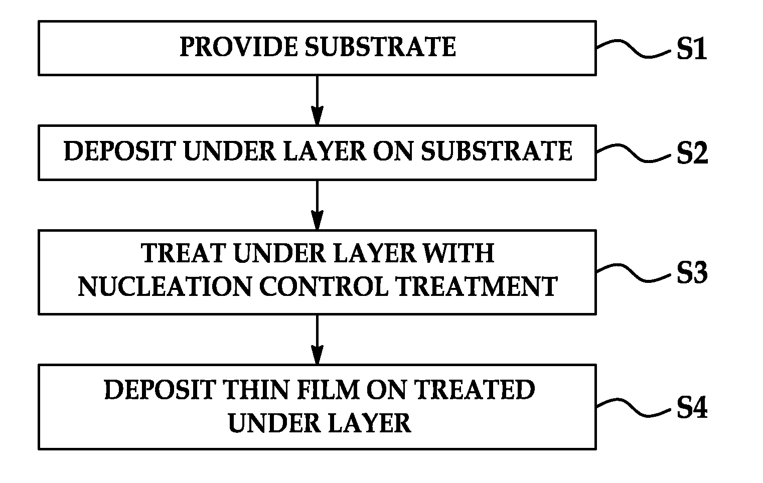
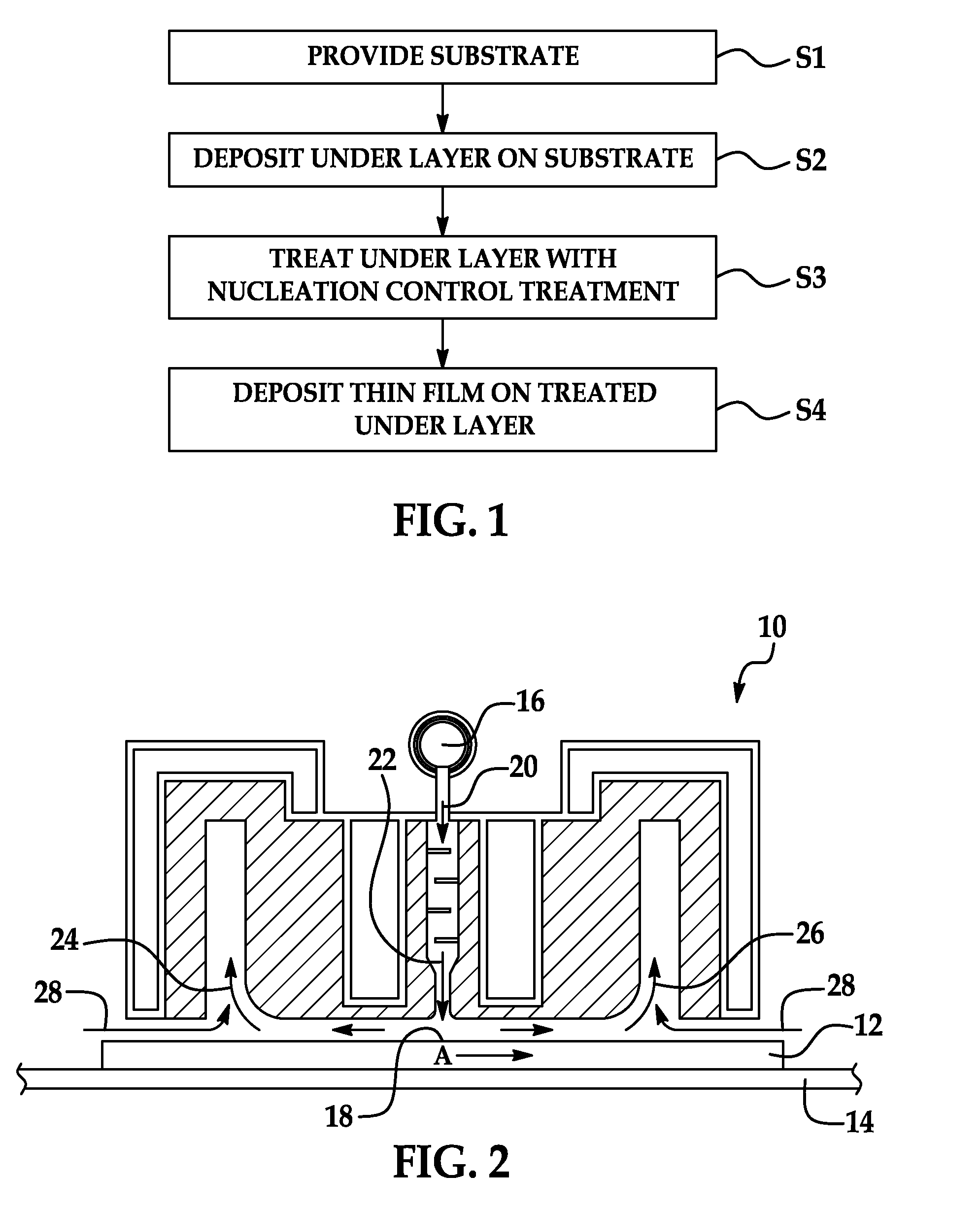
If nucleation is insufficiently controlled, it can lead to reduced adhesion of the thin films to the substrate or to increased susceptibility of such coatings to adhesive initiated failures on aging.
These issues can be most s

Method used


Image

  • Methods of nucleation control in film deposition
  • Methods of nucleation control in film deposition

Examples


experiment example 1

[0042]This example deposits an FTO film directly on a glass substrate. As mentioned above and noted in the results, uncoated glass is a relatively good nucleator for TCO but has long term negative effects on the top coat film.

[0043]A thin film top coat of FTO approximately 300 nm thick was deposited directly on a glass substrate with 40 Kg / hr MBTC; H2O at a molar ratio H2O / MBTC of 1.5; TFAA at a molar ratio MBTC / TFAA of 0.3; and nitrogen as a carrier gas at standard conditions of temperature and pressure (STP) at 70 m3 / hr.

[0044]The resulting thin film surface resistivity (SR) was 18 ohms per square and the resulting haze was 1.5%. Ohms per square is the unit of an electrical measurement of surface resistivity across any given square area of a material.

experiment example 2

[0045]An FTO layer as the thin film is deposited onto an untreated under layer of SiCO results in high haze and low conductivity. A SiCO under layer was deposited on a glass substrate with 0.9 Kg / hr silane, 3.6 Kg / hr ethylene, 3.6 Kg / hr CO2, and nitrogen as a carrier gas at STP at 4.5 m3 / hr.

[0046]A thin film top coat of FTO was deposited on the under layer with 40 Kg / hr MBTC; H2O at a molar ratio H2O / MBTC of 1.5; TFAA at a molar ratio MBTC / TFAA of 0.3; and nitrogen as a carrier gas at STP at 70 m3 / hr.

[0047]Results were variable with the thin film SR varying across the substrate from run to run between approximately 40 ohms per square and 150 ohms per square. Haze was also variable from between about 3% and 7%.

experiment example 3

[0048]A thin film layer of FTO is deposited on an under layer of silica film with carbon incorporated (SiCO) where the SiCO layer is treated with dry air prior to deposition of the FTO thin film layer. The air flow rate is not critical to make a major change in properties of the top coat. In this example, it was set at approximately 3.0 m3 / hr.

[0049]The SiCO under layer was deposited on a glass substrate with 0.9 Kg / hr silane, 3.0 Kg / hr ethylene, 3.0 Kg / hr CO2, and nitrogen as a carrier gas at STP at 8.0 m3 / hr.

[0050]The thin film top coat of FTO approximately 290 nm thick was deposited with 40 Kg / h MBTC; H2O at a molar ratio H2O / MBTC of 3.0; TFAA at a molar ratio MBTC / TFAA of 0.3; and nitrogen as a carrier gas at STP at 70 m3 / hr. The resulting SR was between about 25 to 31 ohms per square with a haze of 1.5%.


PUM

PropertyMeasurementUnit
Sheet resistanceaaaaaaaaaa
Electrical conductivityaaaaaaaaaa

Abstract

Disclosed herein are methods to achieve a significant degree of nucleation control with a chemical vapor deposition based coating approach, by controlling the chemistry of a specifically chosen under layer on a substrate such as glass and then treating this under layer on at least its surface to a specified degree to achieve targeted nucleation control in the second layer film, which is at least partially crystalline.

Description

CROSS REFERENCE TO RELATED APPLICATIONS[0001]This application claims priority to U.S. provisional application Ser. No. 61 / 249,860 filed on Oct. 8, 2009 and incorporated herein in its entirety by reference.FIELD OF THE INVENTION[0002]The present invention relates in general to methods of nucleation control in the deposition of thin films in, for example, float baths. In particular, the chemistry of an under-layer is controlled and then treated on its surface to achieve targeted nucleation control.BACKGROUND[0003]Chemical Vapor Deposition (CVD) has been widely used for many years across a wide range of industrial applications, to produce thin film coatings. In such a process a reactive gas mixture is introduced in the coating region, and a source of energy applied to initiate (or accelerate) a chemical reaction (usually thermal or plasma), resulting in the growth of a coating on the target substrate.[0004]Atmospheric pressure chemical vapor deposition (APCVD) has established itself in...

Claims


Application Information

Patent Timeline
IPC IPC(8): B32B9/04B05D5/12C23C16/40
CPCC03C17/42C03C2217/94C23C16/407C03C2218/322C23C16/0272C03C2218/152C03C17/3441
Inventor SHEEL, DAVID
Owner STEWART ENGINEERS
Why Eureka
Try Eureka