
Single and multi-layer mesh structures for enhanced thermal transport

a mesh structure and thermal transport technology, applied in the direction of lighting and heating apparatus, semiconductor/solid-state device details, separation processes, etc., can solve the problems of high thermal conductivity and fluid mechanics requirements, difficult to cost-effectively scale, and difficult to optimize both chf and htc on the same wicking structure. , to achieve the effect of increasing the boiling nucleation site, critical heat flux, and increasing the mesh pore siz

Active Publication Date: 2021-05-06
UNIV OF COLORADO THE REGENTS OF
View PDF0 Cites 1 Cited by
  • Summary
  • Abstract
  • Description
  • Claims
  • Application Information

AI Technical Summary

Benefits of technology

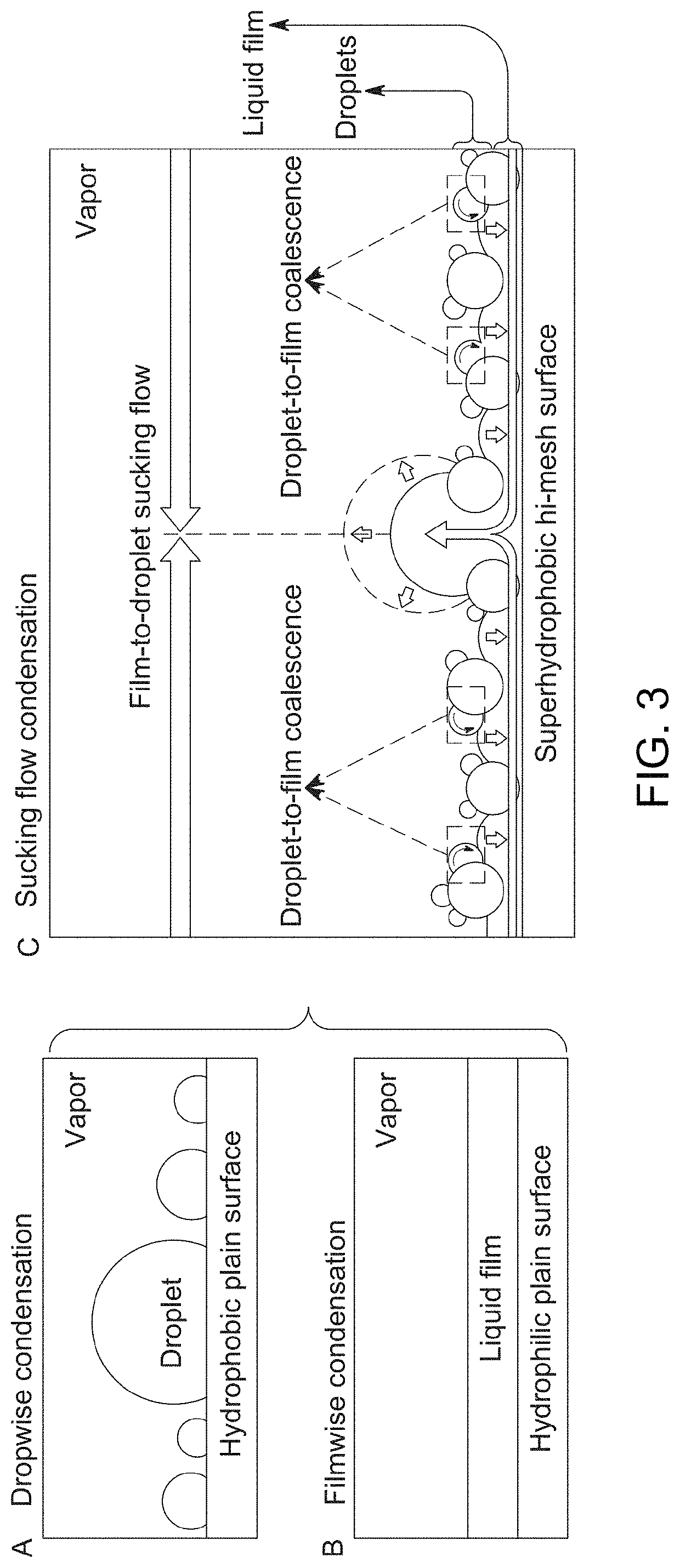
The patent is for a system that uses a multi-layer mesh system with gradient channels for capillary liquid film boiling enhancement. This system includes three or more layers of woven mesh, multi-layer interconnected microchannels, and self-aligned gradient microchannels. These layers have increasing mesh pore size and are bonded to each other and a thermally conducting substrate. The multi-layer interconnected microchannels are formed within and between the layers for capillary liquid wicking. The self-aligned gradient microchannels have increasing mesh pores of increasing size from the layers. This system promotes vapor escape and increases critical heat flux and heat transfer coefficient via capillary liquid film boiling enhancement with accelerated vapor escape for delaying surface dry out.

Problems solved by technology

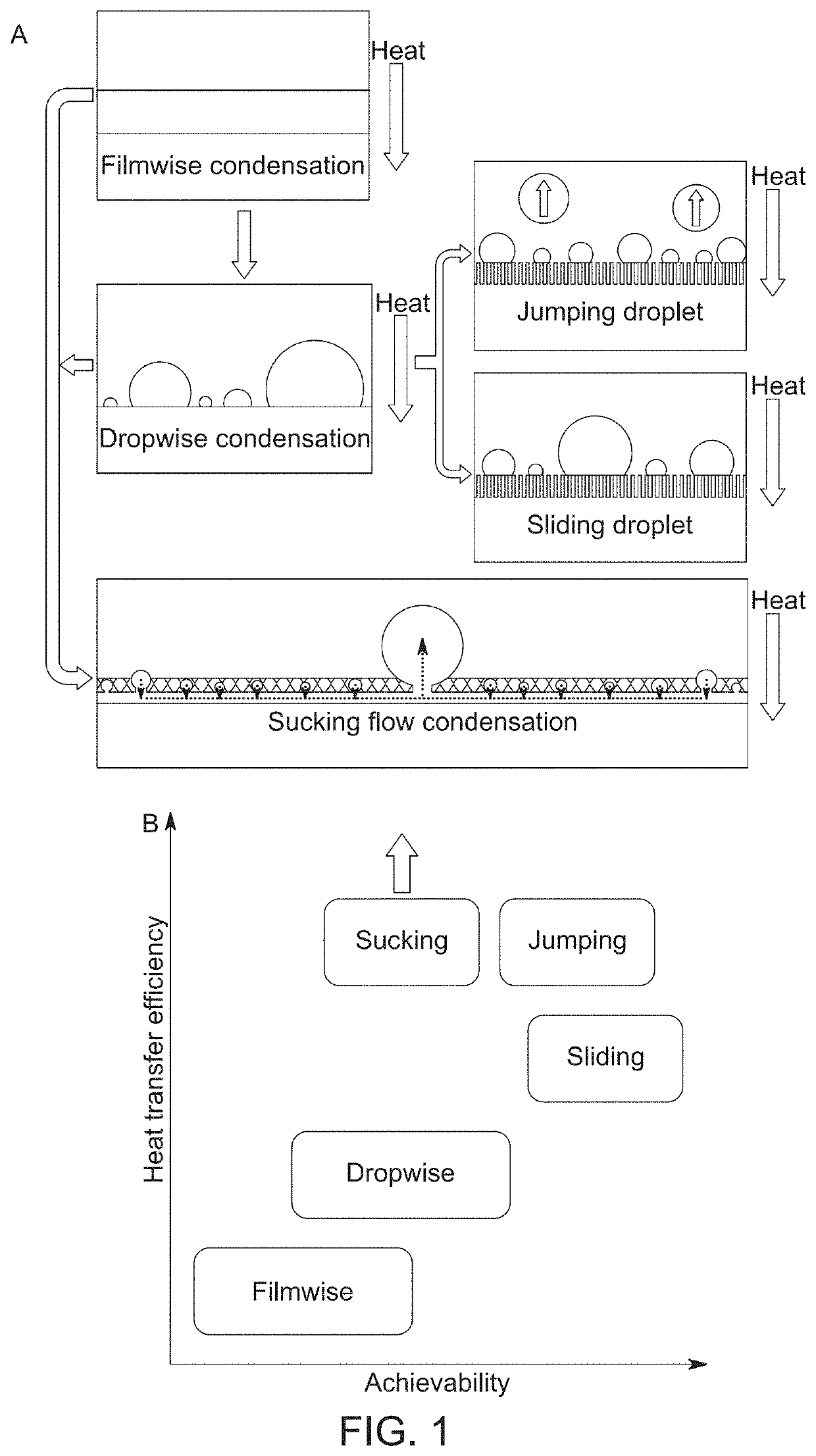
However, the long-standing challenge for better heat transfer performance is to improve simultaneously both surface refreshing and droplet growth on the same surface.
Compared to other water-repellent nanostructured materials for improving self-cleaning and anti-fogging, it is extremely challenging to create large-area structured surfaces cost-effectively on high thermal conductivity substrates to fulfill both fluid mechanics and thermal requirements.
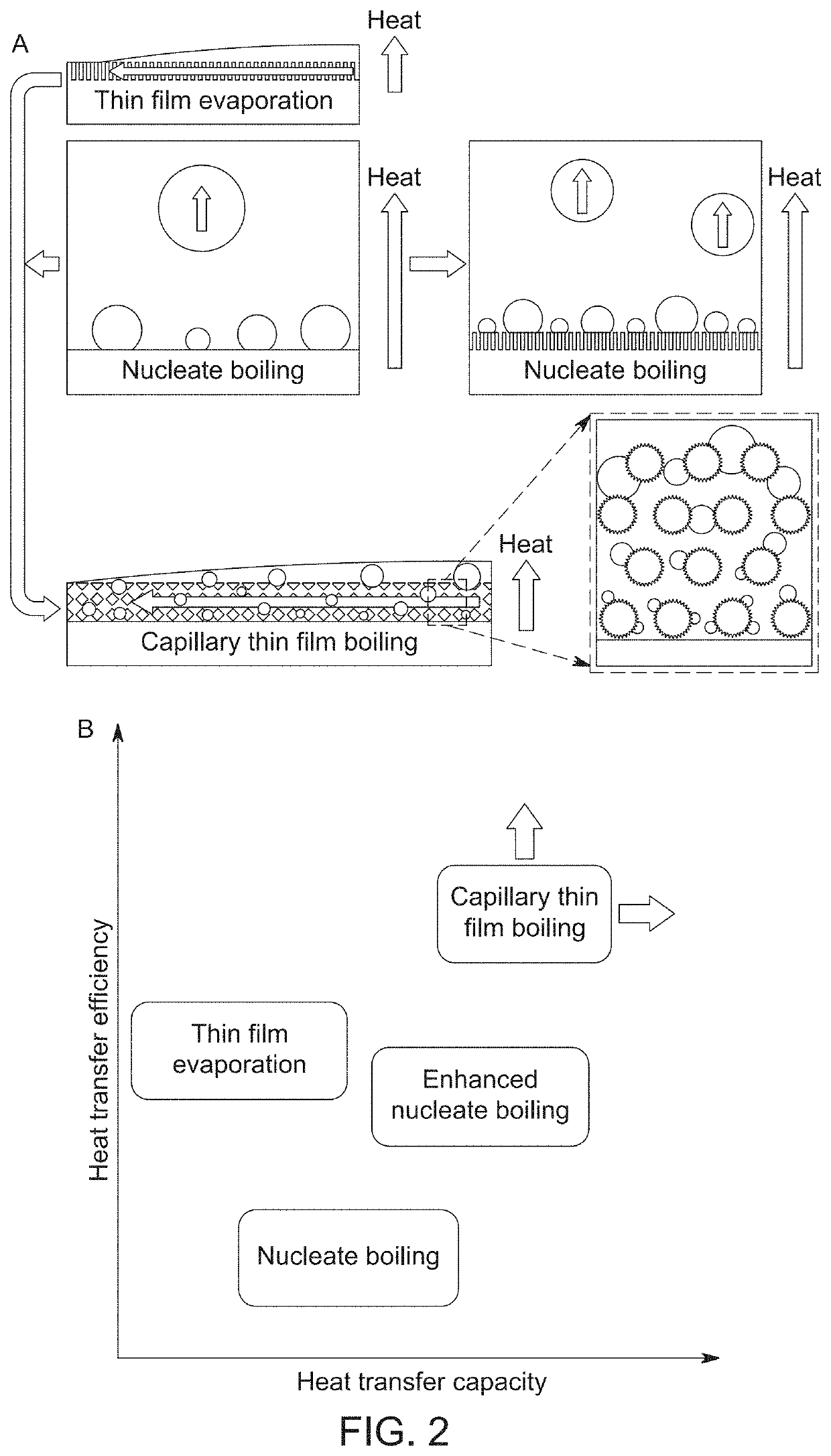
Apparently, these approaches based on pure thin film evaporation suffer from intrinsic tradeoffs between the required high wicking flow rate for liquid supply and the low thermal resistance for heat flow to the evaporation front, which makes it challenging to optimize both the CHF and HTC on the same wicking structure.
Moreover, most of the known wicking structures require delicate nanofabrication, which is challenging to cost-effectively scale.
Thermal management challenges in electronics arise primarily from the exponential increase of power densities and non-uniform distribution of heat sources, with sub-millimeter hotspots with ultra-high heat fluxes in excess of 103 W / cm2 over a planar area of smaller than 10 mm2.
The common heat spreader materials are copper and aluminum, while commercially available expensive alternatives include diamond, SiC, and composites such as diamond / AlN / Mo substrates, which are limited to special applications.
However, the passive strategies in common two-phase heat spreaders based on liquid film evaporation are limited by capillary dry-out, a phenomenon that occurs when a capillary pumping capability of the wicking structure cannot overcome the viscous flow resistance.
A considerable amount of bi-porous wicking structures have been developed to address the conflicting demands on large capillarity and high permeability, however, liquid film evaporation is still limited by the liquid supply and the thermal resistance through the saturated wicking structures.

Method used


Image

  • Single and multi-layer mesh structures for enhanced thermal transport
  • Single and multi-layer mesh structures for enhanced thermal transport
  • Single and multi-layer mesh structures for enhanced thermal transport

Examples


Embodiment Construction

[0083]The word “exemplary” is used herein to mean “serving as an example, instance, or illustration.” Any embodiment described herein as “exemplary” is not necessarily to be construed as preferred or advantageous over other embodiments.

[0084]Preliminary note: the flowcharts and block diagrams in the following Figures illustrate the architecture, functionality, and operation of possible implementations of systems, methods, and computer program products according to various embodiments of the present invention. In this regard, some blocks in these flowcharts or block diagrams may represent a module, segment, or portion of code, which comprises one or more executable instructions for implementing the specified logical function(s). It should also be noted that, in some alternative implementations, the functions noted in the block may occur out of the order noted in the figures. For example, two blocks shown in succession may, in fact, be executed substantially concurrently, or the block...


PUM

PropertyMeasurementUnit
diameteraaaaaaaaaa
diameteraaaaaaaaaa
heightaaaaaaaaaa

Abstract

This disclosure describes single and multi-layer woven meshes designed to enable sucking flow condensation and capillary-driven liquid film boiling, respectively, for instance, in use in heat spreaders. The single-layer woven meshes can include a nanostructure coating and a hydrophobic coating, while the multi-layer meshes can include a microcavity coating and optionally a hydrophilic coating.

Description

CLAIM OF PRIORITY UNDER 35 U.S.C. § 119[0001]The present Application for Patent claims priority to Provisional Application No. 62 / 683,362 entitled “SINGLE AND MULTI-LAYER MESH STRUCTURES FOR ENHANCED THERMAL TRANSPORT” filed Jun. 11, 2018, and Provisional Application No. 62 / 814,066 entitled “THIN FILM BOILING ENABLED ULTRA-HIGH CONDUCTANCE AND HIGH FLUX HEAT SPREADS” filed Mar. 5, 2019, both of which are assigned to the assignee hereof and hereby expressly incorporated by reference herein.FIELD OF THE DISCLOSURE[0002]The present disclosure relates generally to thermal transport structures. In particular, but not by way of limitation, the present disclosure relates to systems, methods, and apparatuses for micro-mesh structures that enhance thermal transport via phase-change processes such as condensation or evaporation / boiling.DESCRIPTION OF RELATED ART[0003]Condensation[0004]Condensation is a ubiquitous phase-change phenomenon that is of vital importance in a broad range of industri...

Claims


Application Information

Patent Timeline
Patent Type & Authority Applications(United States)
IPC IPC(8): F28F13/18F25B39/04
CPCF28F13/182F25B39/04H01L23/427F28D15/046F28F13/185B01D5/0027
Inventor YANG, RONGGUIWEN, RONGFUXU, SHANSHANLEE, YUNG-CHENG
Owner UNIV OF COLORADO THE REGENTS OF
Learn More