[0010]It is an object of the invention to provide a magnetic head which increases the readout resolution by the use of
a Domain Expansion technology based on magnetostatically coupled
layers.
[0012]The
nucleation of small reversed areas in the readout layer of a MAMMOS medium during an initial stage of the readout process, mainly occurs in an area where the stray field is strongest and the stray field direction deviates from the
perpendicular direction, so the in-plane stray field component can exert a torque on the
perpendicular magnetization in the readout layer to induce
nucleation. During readout by means of known devices,
nucleation will, therefore, start, not adjacent to the center of a mark, but adjacent to the mark / non-mark and non-mark / mark transitions. This leads to a broadening of the detection area and thereby to erroneously copied domains during
high resolution readout.
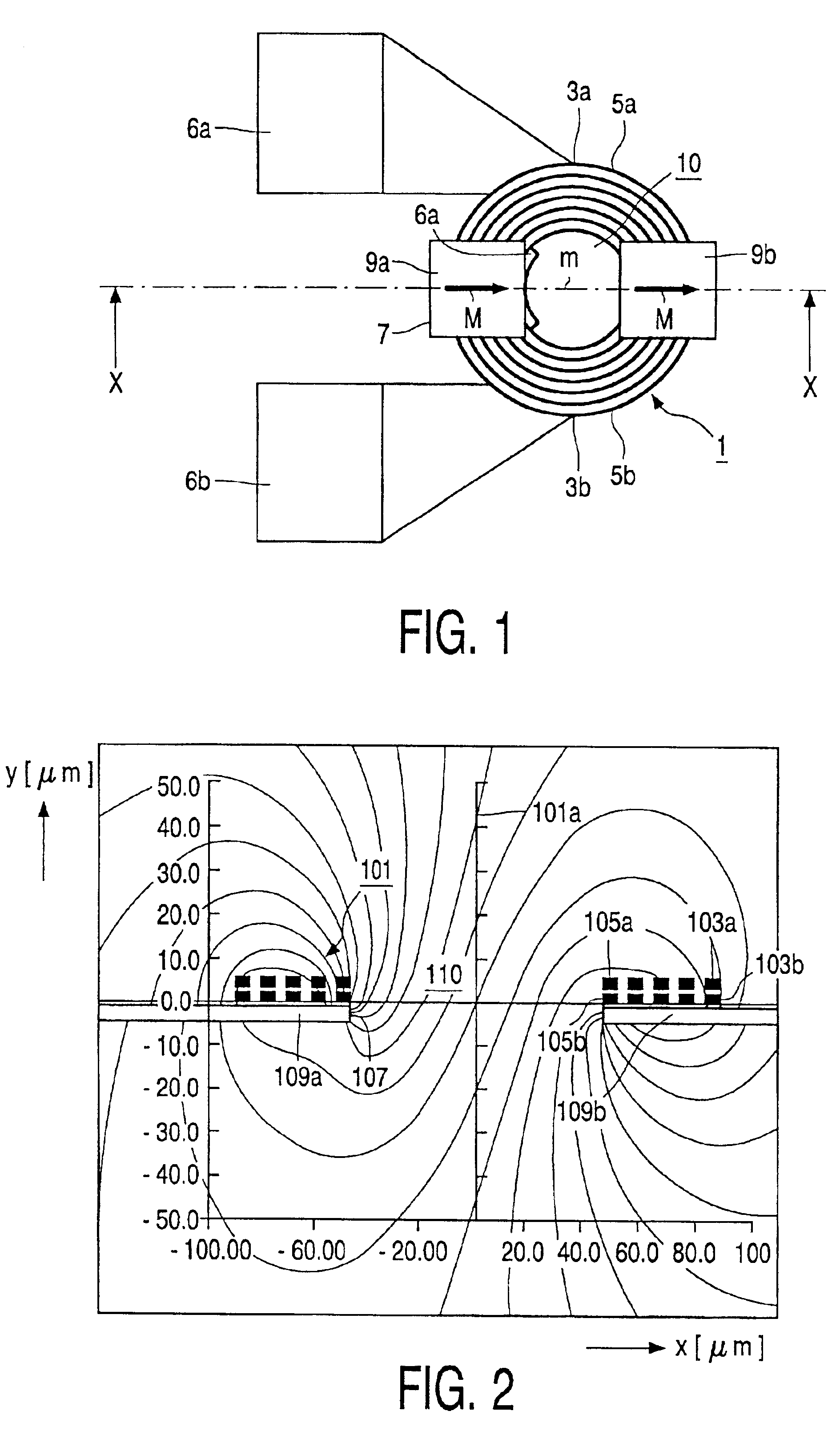
[0013]By using the magnetic head according to the invention, an
external field with a
magnetic field component in a track direction and of sufficient strength, can be generated in order to suppress the disadvantageous effect of erroneously copied domains. The last-mentioned
magnetic field component increases the nucleation of the mark / non-mark transition and reduces the nucleation of a non-mark / mark transition or vice versa depending on the direction of the in-plane field component. Combining the resulting tilted field with the copy window movement during readout, leads to a reduced
Bit Error Rate for small marks and non-marks. An effect of the structure in accordance with the invention is furthermore that an in-plane field component can enhance the initial domain expansion speed, which is advantageous for high data rates. Apart from the above-defined effects, the magnetic head according to the invention has the
advantage that no current is required to generate the in-plane
bias field so that heat dissipation can be kept limited.
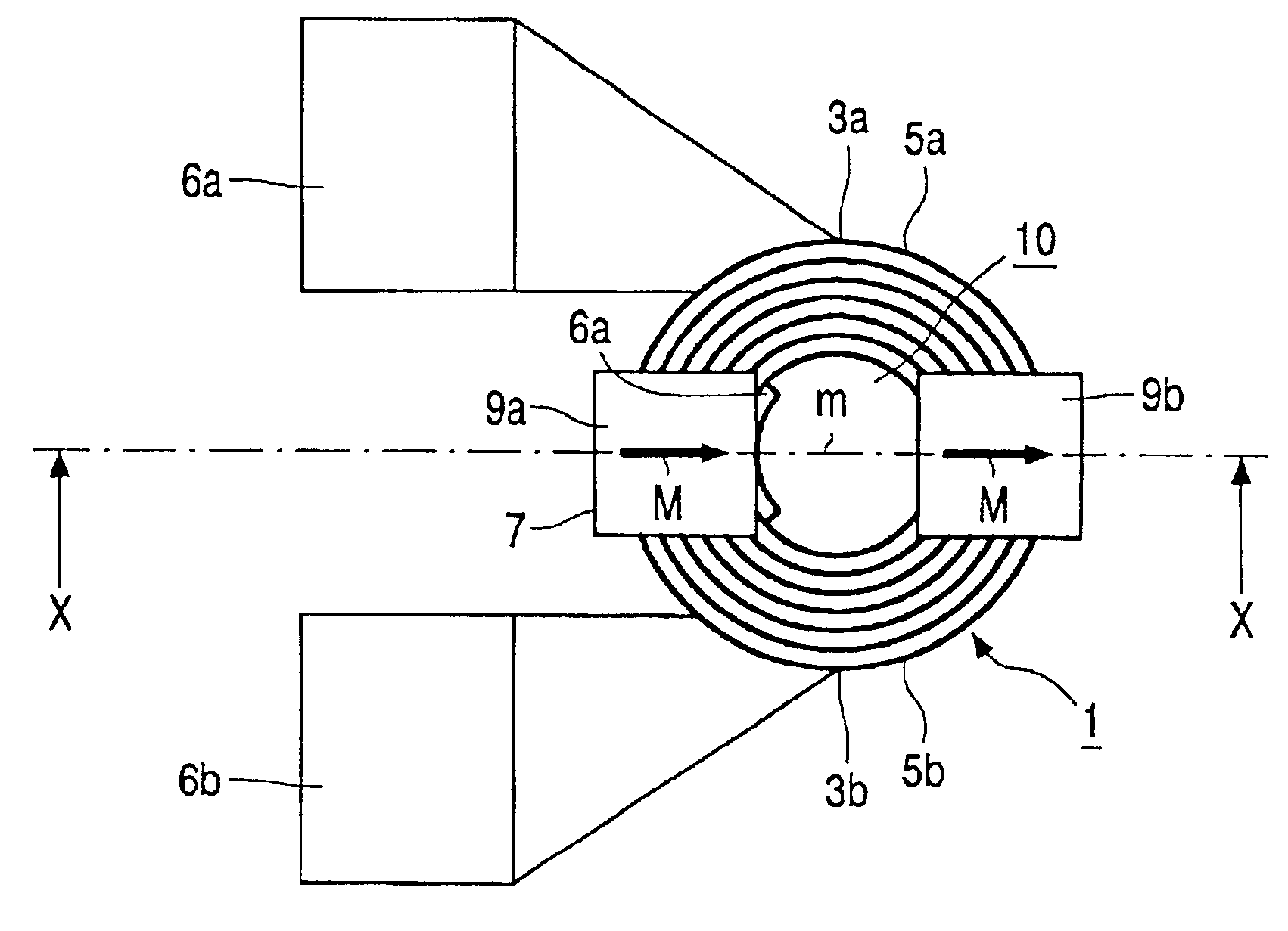
[0014]To obtain high data rates during LP-MFM recording and MAMMOS readout or the like, the magnetic coil should be small and close to the medium. The measures in accordance with the invention are particularly advantageous in a so-called First-Surface or Cover-Layer incident recording configuration, where the coil and the
optical focusing system are present at the same side of the magneto-
optical medium, and a
laser spot is focused through the coil. In this context, an embodiment of the magnetic head according to the invention is characterized in that the magnetic coil has a central area and the conductive winding extends around this central area, and in that the permanent-
magnetic layer structure includes two flat permanent magnets located at opposite sides of the central area of the magnetic coil. The magnets have the same
magnetization direction to generate the desired in-plane field in the central area of the magnetic coil. This embodiment offers the possibility of obtaining a tilted field over a relatively large fraction of the central area of the coil during use without this central area being covered. The central area may be a transparent inner area or an inner aperture. In the case of substrate incident recording, where the magneto-
optical medium extends between the coil and the
optical focusing system and a
laser beam does not pass the coil, an embodiment may be advantageous in which the magnetic coil has a central area and the conductive winding extends around this area, the permanent
magnetic layer structure including a permanent
magnet located in the central area.
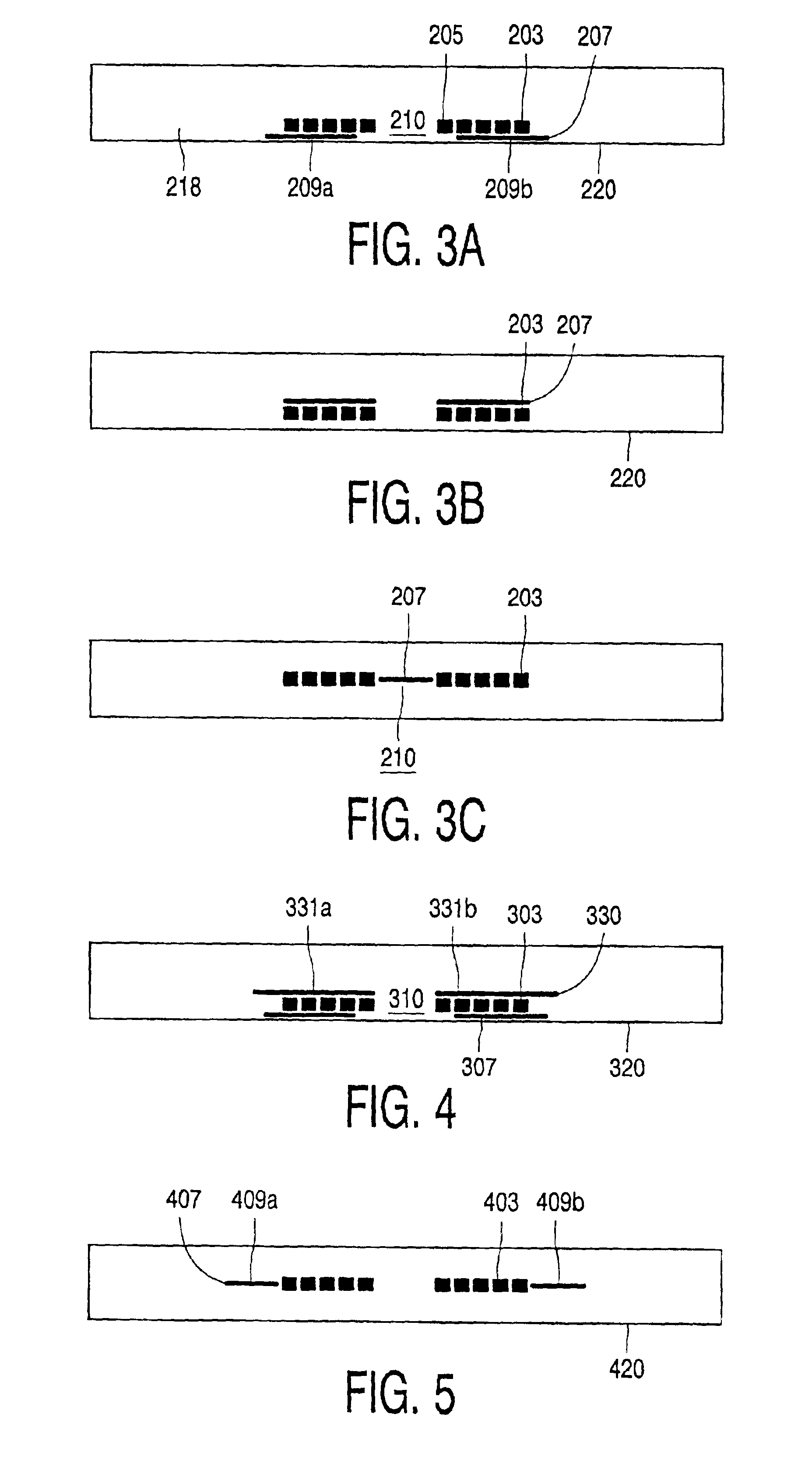
[0017]A further alternative embodiment is characterized in that the permanent-
magnetic layer structure and the coil layer structure are situated in the same plane, the coil layer structure extending between a pair of permanent magnets of the permanent-
magnet layer structure. This embodiment with co-planer structures is advantageous, in particular, if the desired in-plane field component is required across a relatively large area at a relatively
large distance from the coil layer structure.
[0018]Depending on the dimensions of the central area of the magnetic coil and / or, the distance of the coil to the medium during use, a soft magnetic layer structure, extending substantially parallel to the coil layer structure, can be advantageous in enhancing the field in the storage medium generated by the coil. For this reason, an embodiment of the magnetic head according to the invention is provided with such a soft magnetic layer structure. In such an embodiment, the coil layer structure may extend between the permanent-magnet layer structure and the soft magnetic layer structure, or the soft magnetic layer structure may be situated at a side of the coil layer structure, this side being turned away from the head face. The soft magnetic layer structure improves the efficiency of the conductive winding. Moreover, in particular, if the permanent-magnet layer structure and the coil layer structure are situated in the same plane, the efficiency of the permanent magnets is improved by the soft magnetic layer structure. The soft magnetic layer structure may be a continuous soft magnetic film in the case of a recording configuration where the magnetic coil is situated at one side of the medium and the
laser beam is focused to a spot through the substrate of the storage medium. Otherwise, the soft magnetic layer structure may be formed as an interrupted soft magnetic film. Suitable soft magnetic materials for the soft magnetic layer structure are, e.g., NiFe or CoZrNb or FeTaN alloys.

