Liquid removal apparatus

a technology of liquid removal apparatus and liquid filter, which is applied in the direction of moving filter element filter, filtration separation, separation process, etc., can solve the problems of complex system, unsuitable compression technique, unsuitable centrifugal method, etc., and achieves the effect of enhancing product control, reducing liquid content, and reducing liquid conten

Active Publication Date: 2011-04-21
CT CIVIL LTD
View PDF16 Cites 45 Cited by
  • Summary
  • Abstract
  • Description
  • Claims
  • Application Information

AI Technical Summary

Benefits of technology

[0103]In order to obtain optimum liquid extraction from the infeed slurry, it is important to distribute the slurry uniformly across the width of the filter belt and this may be achieved in a variety of means. Moreover, certain slurry compositions are suitable for the pre-filtering of a large percentage of the liquid content which permits uses of further conditioning means.
[0105]an infeed distribution manifold, configured to laterally distribute the infeed slurry across the filter belt.
[0111]A spreader both distributes the slurry laterally and agitates the solids within the slurry liquid. In one embodiment, the spreader is an elongated rotatable shaft equipped with outer projections orientated to defect the slurry evenly across the filter belt. Preferably, said projections include tines, bristle, and / or blades, walls or the like. In one embodiment, the spreader is a formed as a pair of auger sections about a common rotating shaft, wherein the helical flanges forming said auger section are reciprocally orientated away from each other from a central shaft position. The helical / spiral configuration also prevents solid debris becoming lodged on the spreader in addition to distributing the slurry laterally. The spreader may be rotated in either direction causing the slurry distribution to be moved inward or outwards from the slurry flow centre as required.
[0143]The gas-permeable membrane may take any suitable form including synthetic, woven, perforated or mechanical barriers, e.g. metallic wedge-wire. In use, as the flocculated slurry flows into the pre-filtering chamber and is subjected to the effects of the rising gas bubbles as the slurry flows towards the outlet. In one embodiment, the pre-filtering chamber is divided into a lifting portion and an extraction chamber. The lifting portion is configured to be of sufficient length to allow the rising bubbles to lift the solids to the upper first strata above the height of the gas-permeable membrane. The remaining slurry liquid is substantially clean liquid is removed from the extraction outlet, leaving the remaining slurry with a substantially higher solids content. The liquid removal apparatus thus receives a slurry product with a significantly lower liquid content, enhancing the product control that may be exercised during the further liquid extraction stages.
[0150]Preferably, said solids barrier is formed as a ‘blanket’ layer of flocculant additive material, preventing passage of the slurry solids flocculated to the flocculant additive. Preferably said pre-filtering chamber configuration includes a portion with a variable horizontal cross-sectional area (i.e. an at least partially tapered, inclined or conical portion, herein referred to as the ‘expansion’ section), such that as slurry flow rates vary, the suspended solids barrier moves up or down said expansion section with a corresponding variation in the surface area occupied by the barrier. The liquid extraction outlet is preferably configured to collect settled clear liquid overflowing from said upper strata of the pre-filtering chamber.
[0165]The surface wiper is formed as a substantially inclined sheet or member producing an elongated tapering slot between the lower wiper surface and the upper filter belt surface (said second side). Consequently, the surface wiper applies a slight compressive force onto the upper surface of the slurry / particulate-product exiting the manifold, forcing some liquid through the slurry solids. The wiper also applies a frictional, abrasive force to the upper surface of the product, causing the upper layer of particles to shear from their adjacent lower layer and generating small cracks and fissure in the upper product surface. These surface cracks provide air and liquid channels through the product and prevent the upper surface forming an effectively impenetrable layer.

Problems solved by technology

It will be clear that each of the aforementioned methods have attendant advantages and disadvantages in processing different mixture-types, e.g. compression techniques may not be suitable for mixtures with a low solids concentration and a centrifugal method may not be suitable where the solids are sharp and abrasive.
While such prior art systems may be effective at achieving a high reduction in water content in most applications, there are a number of inherent disadvantages in using such complex systems, as described below.
Belt-based systems such as the Thissen, Prinssen and Marchal systems can prove expensive as the supporting rubber belts used often need replacing as they become stretched or damaged under the large stresses caused by the vacuum and weight of the mixture.
Replacing belts can prove costly in terms of materials and operational delay.
Moreover, such systems typically only apply the vacuum via the apertures in the belts, which can be small or narrow, thus potentially not evacuating liquid evenly through the filter medium.
However, the vacuum chamber is inherently more difficult to seal against the mesh screen of the El-Hindi systems and thus requires a complicated sealing mechanism in order to function properly.

Method used


Image

  • Liquid removal apparatus
  • Liquid removal apparatus
  • Liquid removal apparatus

Examples


Embodiment Construction

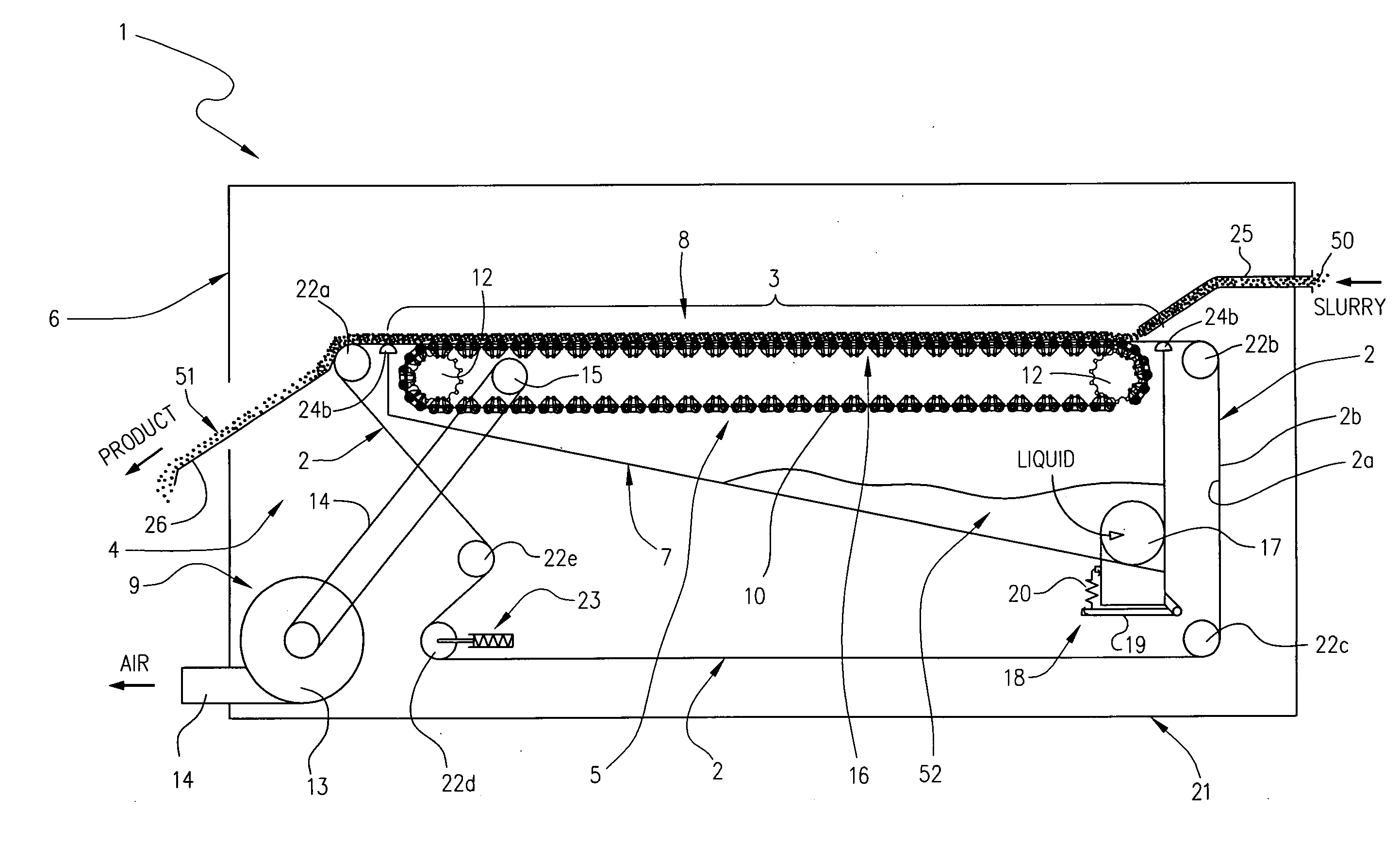
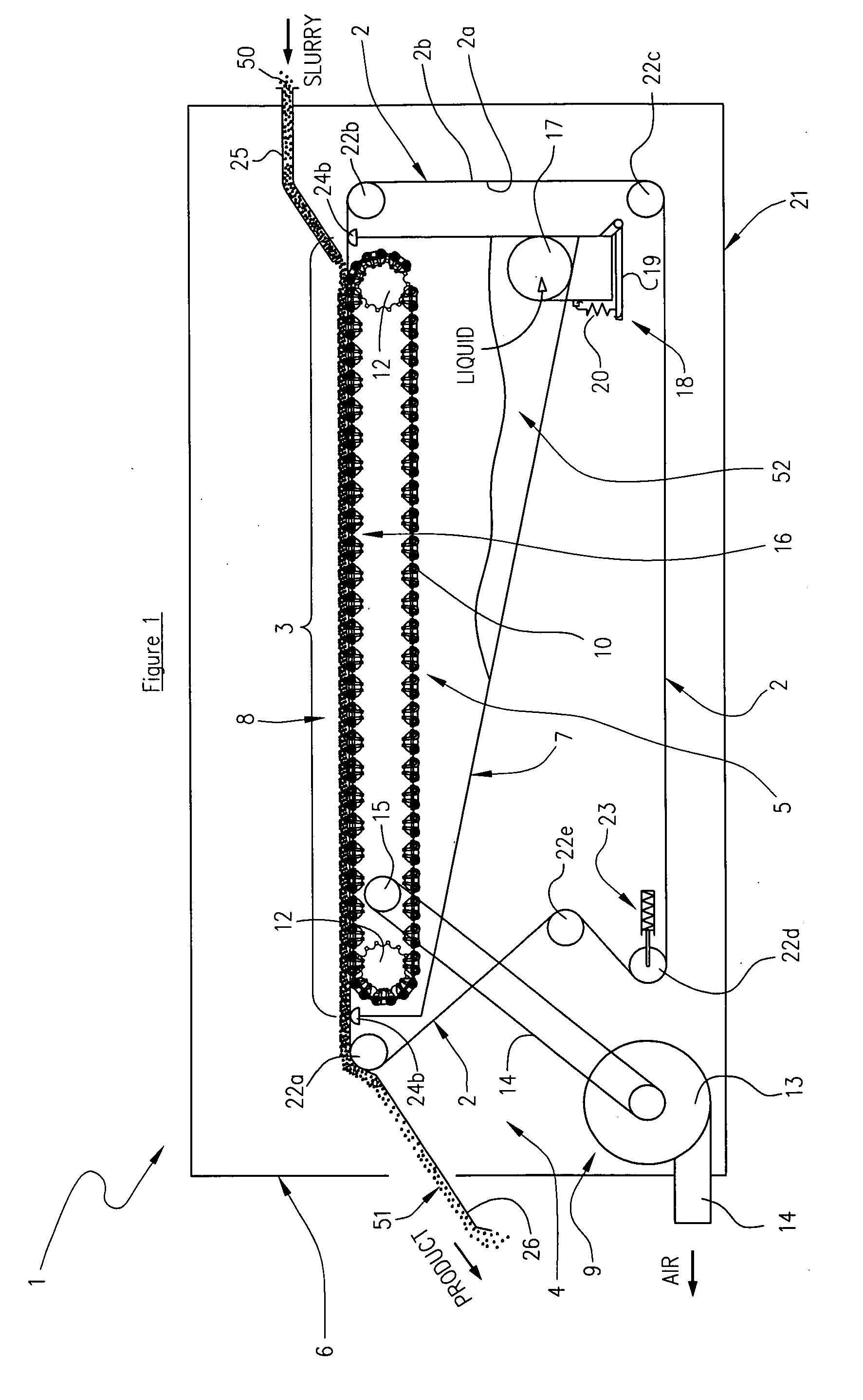
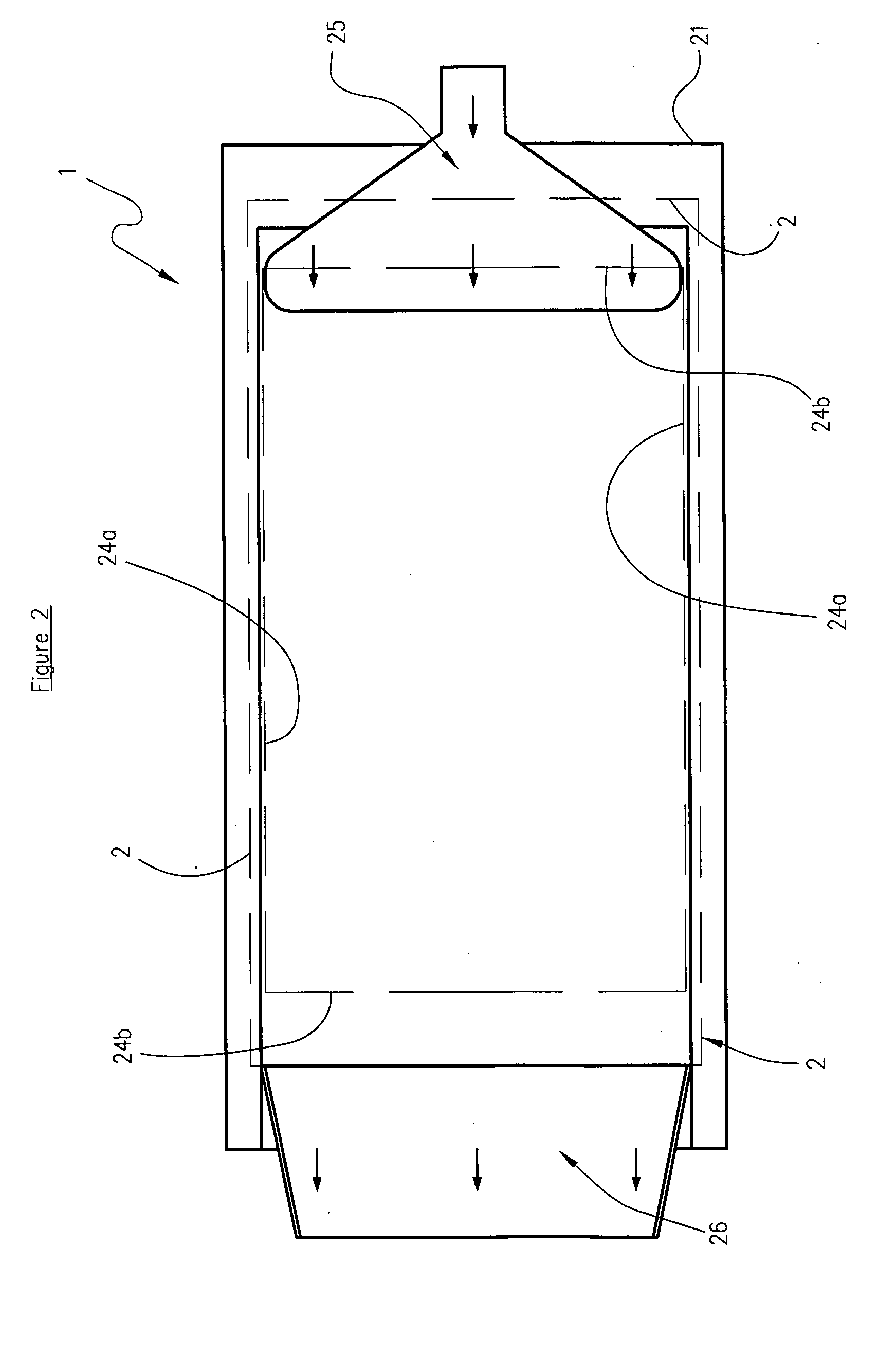
[0302]FIGS. 1 to 4 show a first example of a liquid removal apparatus (1) according to one preferred embodiment of the present invention. The liquid removal apparatus (1) is adapted to at least partially separate liquid from an infeed composite slurry (50) of liquid and solids.

[0303]The liquid removal apparatus (1) has a movable, permeable membrane provided in the form of filter belt (2) having a first side (2a) and an opposing second side (2b). At least a portion (hereinafter termed the ‘loaded belt portion’ (3)) of the second side (2b) is configured to receive the slurry (50). The filter belt (2) is liquid permeable but substantially impermeable to the solid content of the slurry (50) such that the majority of the solids content is prevented from passing through.

[0304]The liquid removal apparatus (1) has a permeable membrane support system (4) configured to provide a movable support for the loaded belt portion (3). The support system (4) has a transport deck (5) located in contact...


PUM

PropertyMeasurementUnit
permeableaaaaaaaaaa
pressureaaaaaaaaaa
flexibleaaaaaaaaaa

Abstract

A liquid removal apparatus adapted to separate liquid from a composite slurry of liquid and solids. The apparatus includes a movable, permeable membrane having opposing first and second sides. A ‘loaded belt portion’ of the second side is configured to receive the slurry. A permeable membrane support system is configured to provide movable support for the loaded belt portion and includes a transport deck located in contact with the first side of the permeable membrane below the loaded belt portion. The liquid removal apparatus has a housing with a low-pressure chamber in sealing contact with the first side of the permeable membrane. A pressure conditioning system applies a differential pressure via the housing to generate a lower pressure on the first filter belt side than on the second side. The transport deck is located within the low pressure chamber.

Description

TECHNICAL FIELD[0001]This invention relates to a liquid removal apparatus, and in particular, but not exclusively, to a dewatering apparatus for use in removing a significant proportion of the water from a sludge or slurry composed of liquids and solids.STATEMENT OF RELATED APPLICATIONS[0002]This application claims priority from the provisional specification filed with respect to New Zealand patent application number 566710 and the content of this documents is herein incorporated by reference.BACKGROUND ART[0003]There are many applications where it is necessary to remove a liquid from a mixture of solids and liquids. The solids are typically suspended in the liquid or, in low liquid concentrations, the liquid may be bound to the solids, e.g. absorbed by the solids.[0004]A common example of these applications is in the recycling of liquid and solids from industrial by-products or waste. Here, the liquid may be used as a transport medium for the solids or used in the processing of a p...

Claims


Application Information

Patent Timeline
Patent Type & Authority Applications(United States)
IPC IPC(8): B01D33/04B01D33/056B01D33/74
CPCB01D33/04B01D33/745B01D2201/204B01D33/056B01D33/37B01D33/41B01D33/705
Inventor SMITH, GARY LEWIS
Owner CT CIVIL LTD
Why Eureka
Try Eureka