Power generating buoy

a technology of power generation buoys and buoys, which is applied in the direction of electric generator control, machines/engines, mechanical equipment, etc., can solve the problems of inability to deploy densely on low-power remote sensor platforms, limited operation life of small remote buoys, and weight over 1000 kg, so as to achieve greater differential force, compactness, and light weight

Inactive Publication Date: 2011-04-21
TREX ENTERPARISES CORP
View PDF6 Cites 31 Cited by
  • Summary
  • Abstract
  • Description
  • Claims
  • Application Information

AI Technical Summary

Benefits of technology

[0011]The preferred embodiment is a buoy for generating energy from wave motion which is more compact and lighter weight than what is available on the market today. It relies on an underwater sail tethered to an inflatable float at the surface that allows it to generate 100 W from a package that only weighs 100 kg (220 lbs). The inflatable float at

Problems solved by technology

The operating lifetime of small remote buoys is limited by onboard battery power.
This is inconvenient, and often impractical to the point that many compact sono-buoys are designed to scuttle themselves af

Method used


Image

  • Power generating buoy
  • Power generating buoy
  • Power generating buoy

Examples


Embodiment Construction

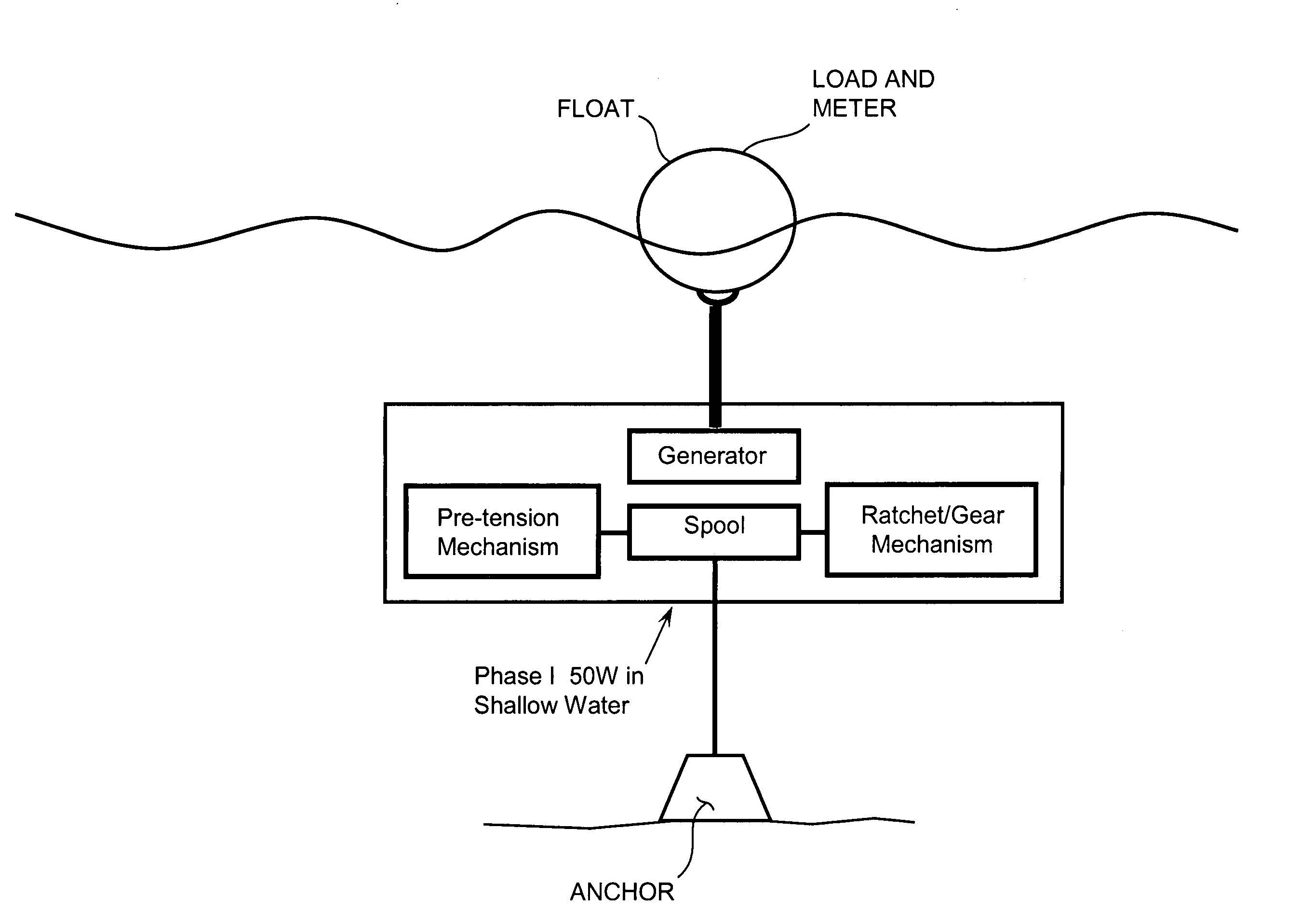
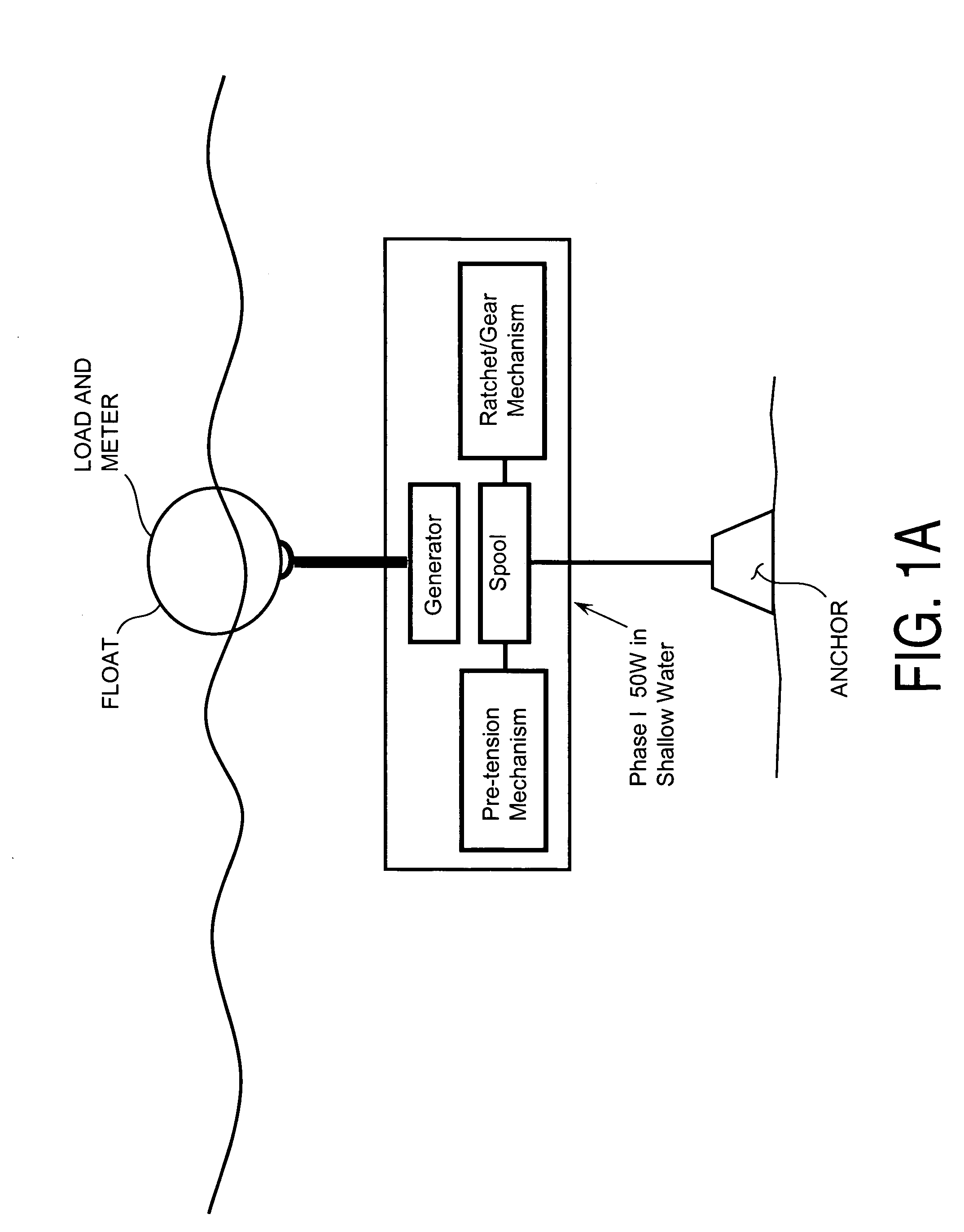
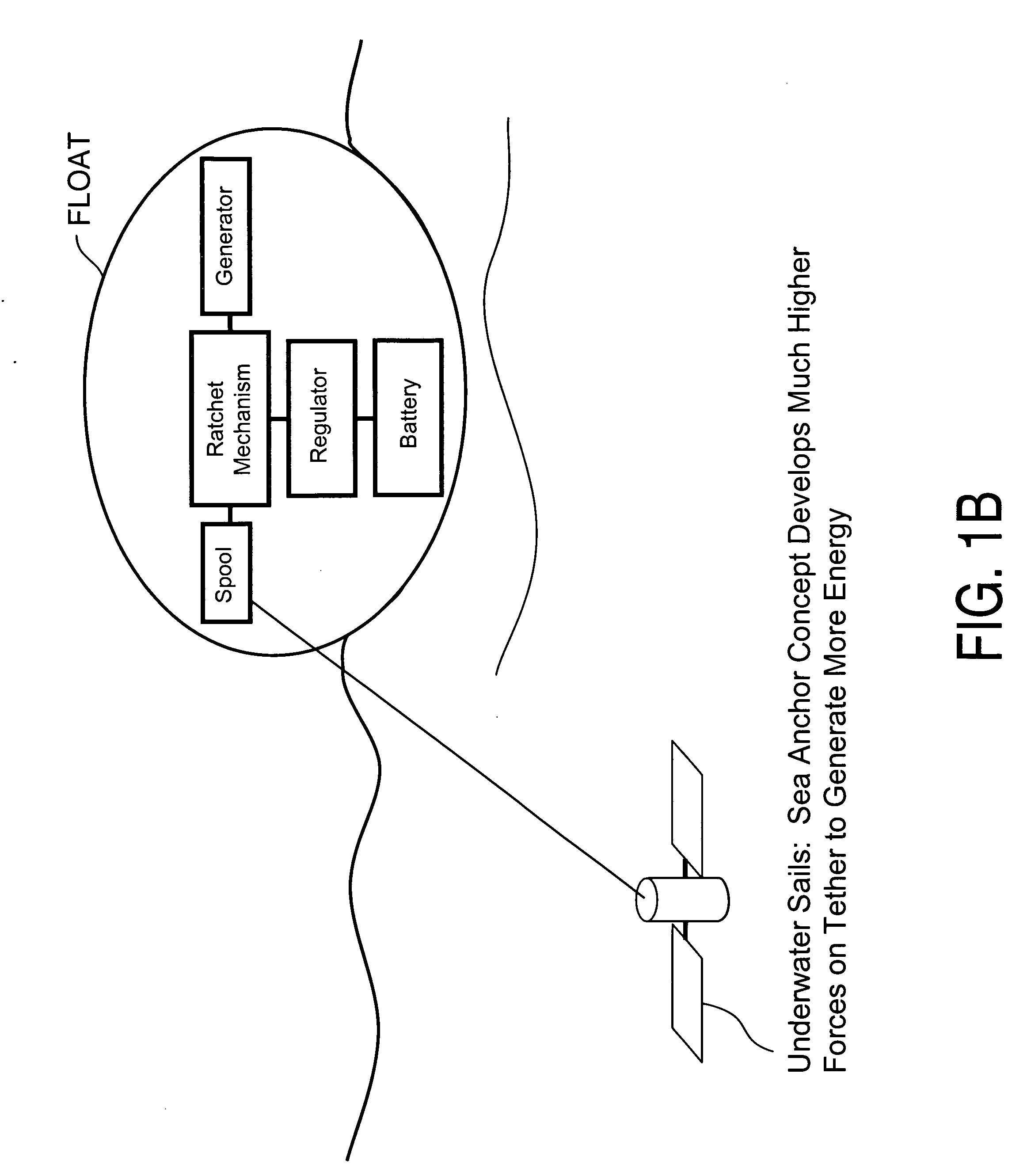
[0020]Applicants have successfully designed and built a prototype compact wave energy device and successfully tested this prototype a power in excess of 50 W. This device utilizes an inflatable float at the surface tethered to either an anchor or underwater sail that allows it to generate maximum energy from a package of a given deployment size and weight.

[0021]The basic concept of the invention is a pull-cord generator coupled to surface float, preferably an inflatable surface float. Simulations developed by Applicants answer questions such as the sea state required to generate a given amount of power for this arrangement given a certain size float and set of allowable forces. The models will also help examine the anticipated sizing of the components for the ultimate full 100-200 W operation in the future.

[0022]To calculate how much energy can be generated from such an arrangement, we look at typical sea states:[0023]Sea State 3: 0.5-1.25 m Wave Height[0024]Sea state 4: 1.25-2.5 m ...


PUM


Abstract

An electric power generating buoy capable of generating power by scavenging energy from ocean wave motion. The power generating buoy includes float element adapted to float up and down following wave motion and an electric generator system with a spring loaded spool mechanism adapted to drive the rotor of the electric generator. It also includes an anchor element and a tension element attached to an anchor and the spring loaded spool mechanism and adapted to spin the spring loaded spool mechanism to generate electric current when wave action causes the float element to rise relative to the anchor element. Preferred embodiments of the buoy will deliver a minimum of 100 Watts of average power from the wave motion characteristic of moderate sea state (sea state 3), with less power from slight sea state (sea state 2) and more power from higher sea states. The basic power generation scheme will rely on harnessing the mechanical energy of the wave as it repeatedly pushes the buoyant surface float against a ballast force through the distance corresponding to the wave height.

Description

CROSS REFERENCE TO RELATED APPLICATIONS[0001]This application claims the benefit of Provisional Patent Application Ser. No. 61 / 067,157 filed Feb. 26, 2008.FEDERALLY SPONSORED RESEARCH[0002]The invention described in this application was made in the course of work performed under Contract No. N00014-08-M-0275 with the United States Navy and the United States government has rights in the invention.FIELD OF THE INVENTION[0003]The present invention relates to electric generators and in particular to electric generators driven by wave motion.BACKGROUND OF THE INVENTION[0004]Remote ocean instrumentation and monitoring techniques often rely on floating buoys with a variety of sensors to perform missions such as ambient noise measurement, acoustic tracking or communications. The operating lifetime of small remote buoys is limited by onboard battery power. Remote acoustic sensors with hydrophone arrays, onboard RF transmitters, GPS receivers and other support electronics can draw up to 100 W...

Claims


Application Information

Patent Timeline
IPC IPC(8): F03B13/18F03B13/20
CPCF03B13/1865F03B13/20Y02E10/38F05B2240/97F05B2240/917Y02E10/30
Inventor PETTETLOVBERG, JOHNJOHNSON, PAUL
Owner TREX ENTERPARISES CORP
Why Eureka
Try Eureka