Air supply unit for a fuel cell stack, fuel cell system and method for operating an air supply unit

a fuel cell and air supply unit technology, applied in the direction of machines/engines, cell components, electrochemical generators, etc., can solve the problems of particularly high energy release, and achieve the effect of simple and cost-efficient, high efficiency and simple and cost-efficien

Inactive Publication Date: 2011-04-28
DAIMLER AG
View PDF3 Cites 17 Cited by
  • Summary
  • Abstract
  • Description
  • Claims
  • Application Information

AI Technical Summary

Benefits of technology

[0027]Depending on the position of the rotary slide, all the gas from the combustion chamber and the exhaust air of the fuel cell stack can be fed mixed to the first spiral channel and the second spiral channel. Such a dosing device permits an adaptation of the supply of the exhaust air and / or the exhaust gas to the turbine with high efficiency depending on the respectively available momentary mass flow of the exhaust gas or the exhaust air. By means of the dosing device, a variable admission of gas to a two-flow turbine having a non-variable geometry can be achieved in a particularly simple and cost-efficient manner.
[0028]It is furthermore advantageous if the turbine is formed as a, in particular variable twin-flow turbine or segment turbine. With the twin-flow turbine, the variability can be achieved in a particularly simple and cost-efficient manner by means of the dosing device connected upstream thereof. However, variable twin-flow turbines can also be controllable at the turbine, for example by providing an axial slider. In contrast to this, a change of the flow rate behavior can be adjusted with the segment turbine by means of a rotatable tongue ring or the like, wherein a transfer of exhaust gas or exhaust air into the second or first spiral channel can be caused. Such a segment turbine is particularly simple and cost-efficient with regard to its construction. A segment turbine with a rigid, non-variable geometry however enables an effective drive of the compressor by means of the booster function.
[0029]It is furthermore advantageous if a common storage container is provided for storing fuel for the combustion chamber and the fuel cell stack. A complexity of the device is reduced thereby. The fuel can in particular be hydrogen gas.

Problems solved by technology

If compressed air is thus supplied to the combustion chamber as an oxidation means, in the combustion chamber a radial chain reaction takes place after the supply of the fuel and after ignition causing a particularly high energy release.

Method used


Image

  • Air supply unit for a fuel cell stack, fuel cell system and method for operating an air supply unit
  • Air supply unit for a fuel cell stack, fuel cell system and method for operating an air supply unit
  • Air supply unit for a fuel cell stack, fuel cell system and method for operating an air supply unit

Examples


first embodiment

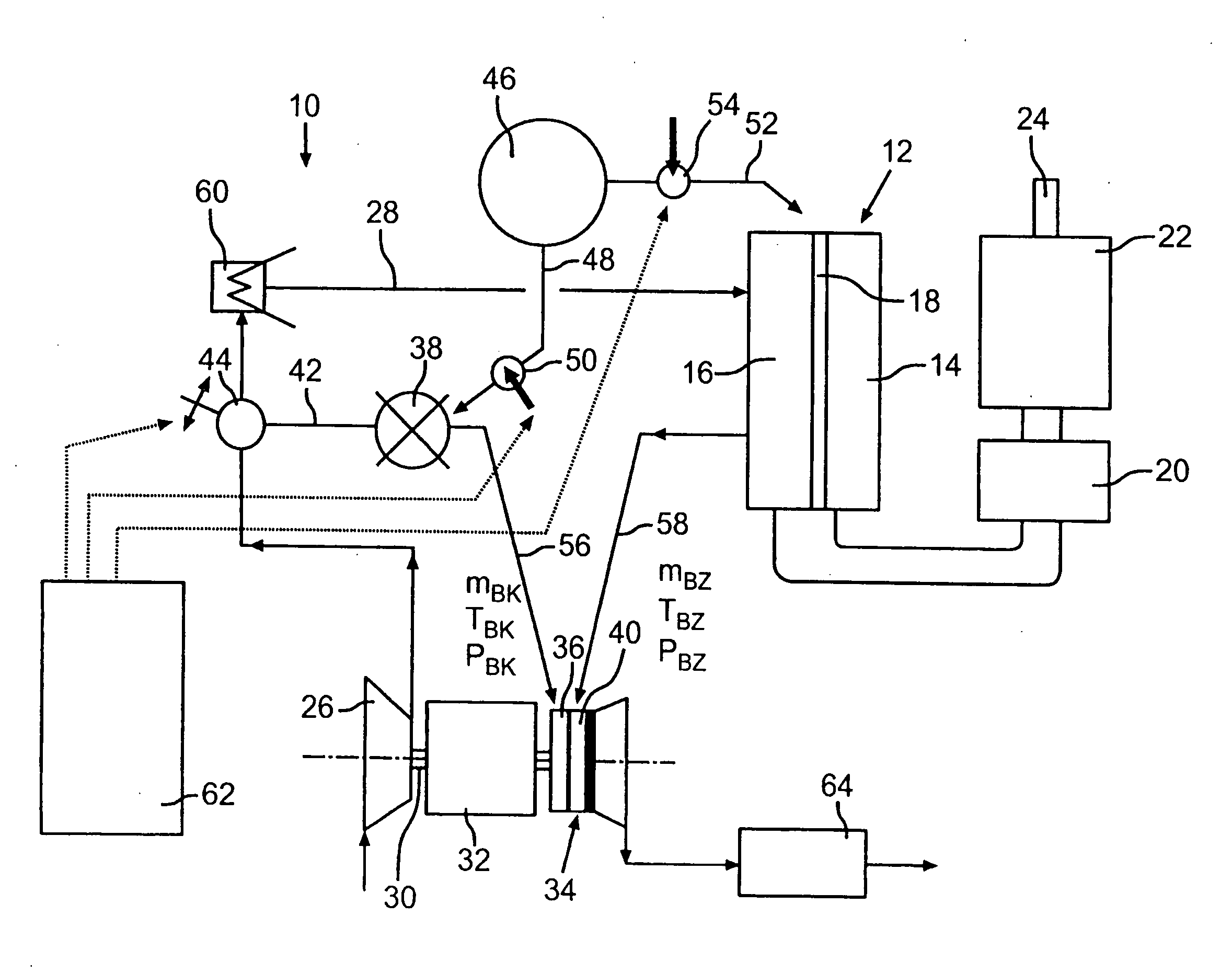
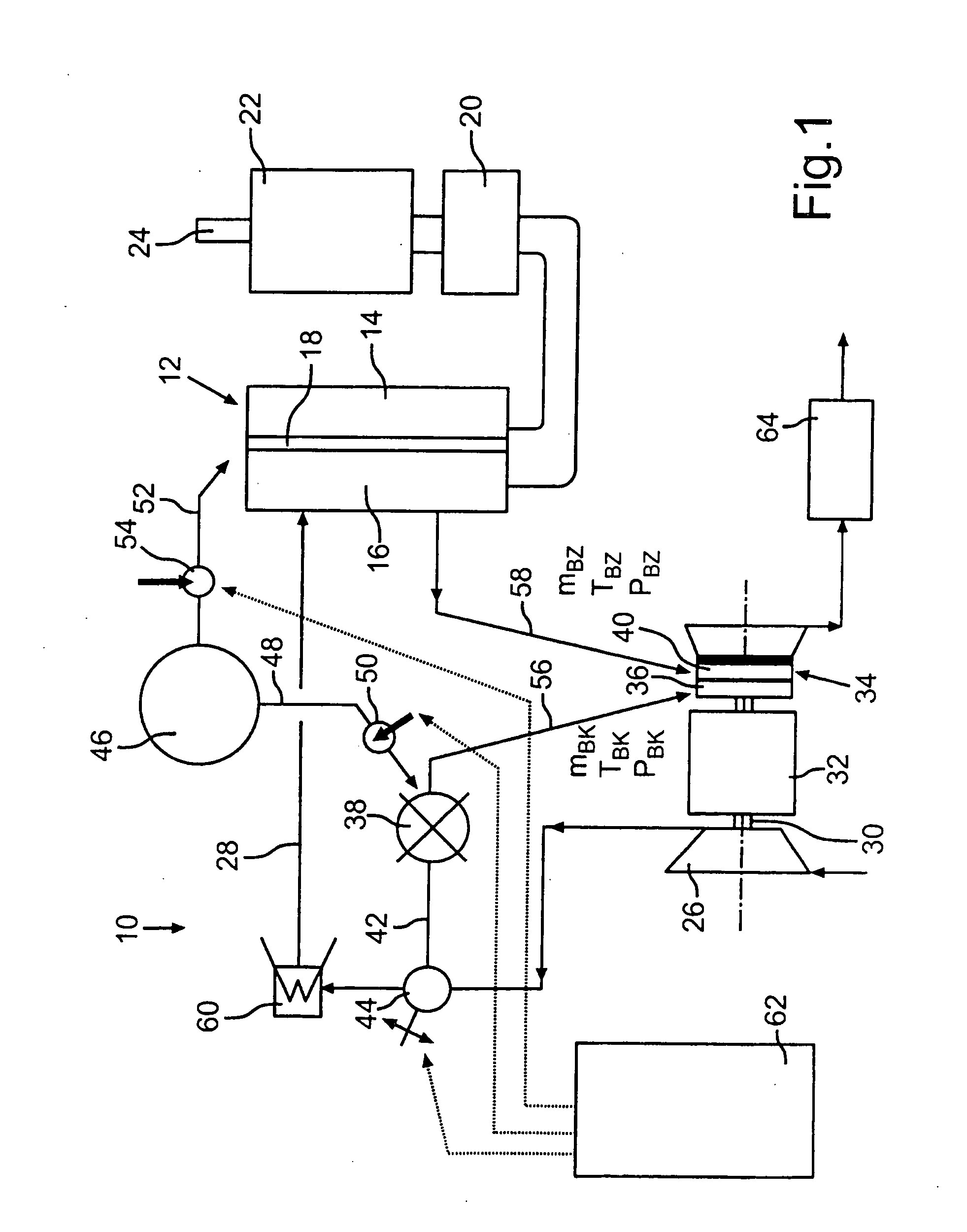
[0043]FIG. 1 schematically shows an air supply unit 10 for supplying air to a fuel cell stack 12. The fuel cell stack 12 includes a plurality of individual fuel cells, wherein an anode chamber 14 is separated from a cathode chamber 16 by means of a membrane 18. The fuel cell stack 12 is connected to an accumulator 20 in an electrically conductive manner for storing the electrical energy generated by means of the fuel cell stack 12. The accumulator 20 is on its part connected to an electrical drive assembly, so that a drive train 24 of a motor vehicle (not shown) can be supplied with drive energy.

[0044]The air supply unit 10 comprises a compressor 26, by means of which compressed air can be fed to the fuel stack 12 via a feed line 28. For driving a shaft 30 of the compressor 26, an electrical drive assembly in the form of an electric motor 32 is provided. Furthermore, a two-flow turbine 34 is arranged at the shaft 30 of the compressor 26, by means of which turbine a compressor wheel ...

second embodiment

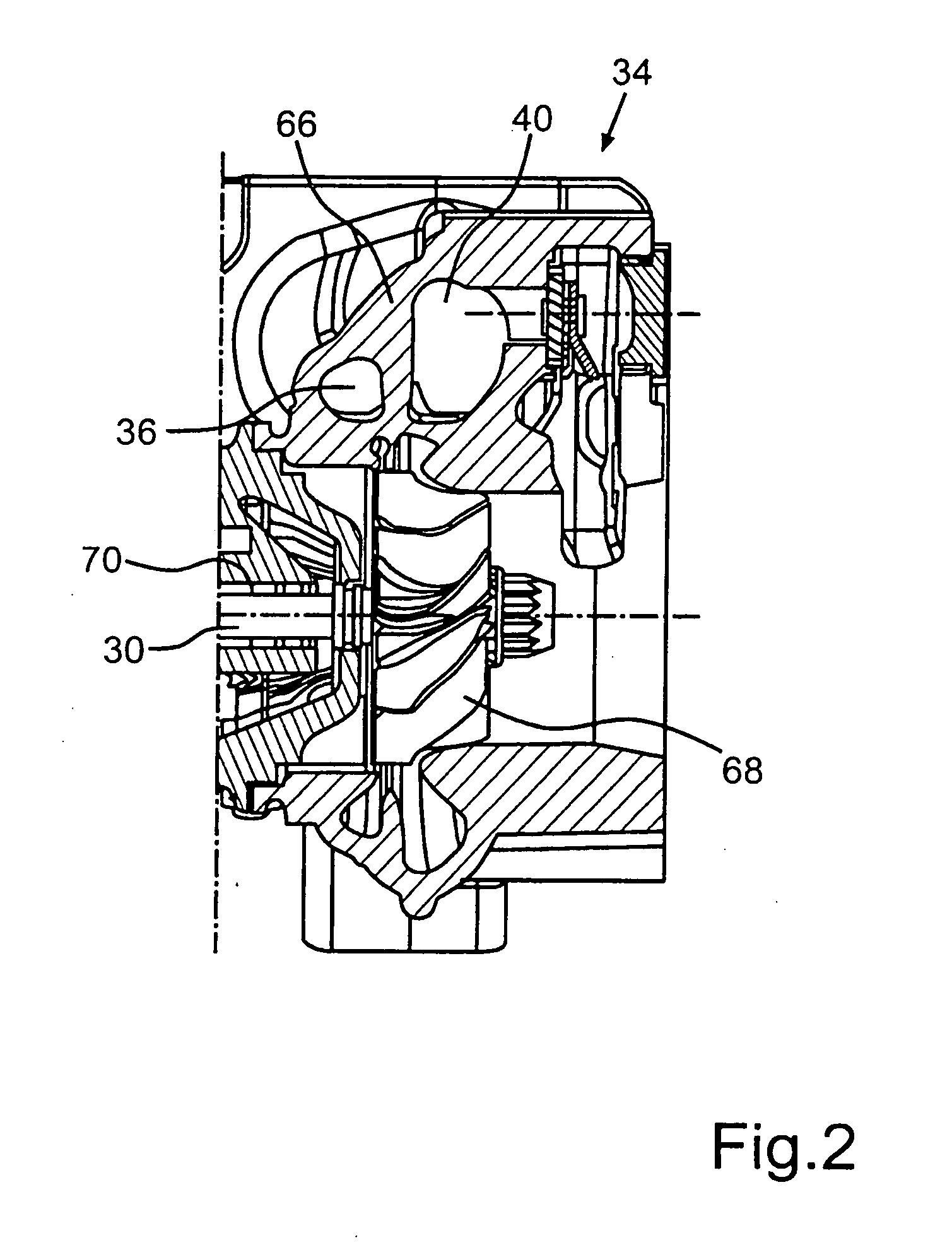
[0051]FIG. 3 shows the air supply unit 10, wherein compressed air is supplied to the fuel cell stack 12 in two stages. A low pressure compressor 72 is hereby connected upstream of the compressor 26, which low pressure compressor is driven by means of the electric motor 32. In contrast to this, the shaft 30 of the compressor 26 is not driven by an electric motor, but via a two-flow turbine 74, which is formed as an asymmetric segment turbine. In an analogous manner to the twin-flow turbine shown in FIG. 1, the turbine 74 according to FIG. 3 has a first spiral channel 36 and a second spiral channel 40. Hereby, the first spiral channel 36 can be supplied with the exhaust gas of the combustion chamber 38, and the second spiral channel 40 with the exhaust air of the fuel cell stack 12.

[0052]The compressor 26, which presently functions as a high pressure compressor that can be operated in a particularly efficiency-favorable manner, has the energies of the exhaust gas of the combustion cha...


PUM

PropertyMeasurementUnit
inlet temperaturesaaaaaaaaaa
electrical energyaaaaaaaaaa
mass flowaaaaaaaaaa

Abstract

In an air supply unit for a fuel cell stack comprising a compressor for compressing air that is fed via a feed line to the fuel cell stack and to a turbine to which also exhaust gas of a combustion chamber can be supplied and wherein an exhaust gas from the combustion chamber is supplied to the turbine, the feed line to the fuel cell stack is in communication with a branch line by way of which compressed air can be fed also to the combustion chamber. The invention further relates to a method for operating an air supply unit for the fuel cell system.

Description

[0001]This is a Continuation-In-Part Application of pending international patent application PCT / EP2009 / 006551 filed Sep. 9, 2009 and claiming the priority of German patent application 10 2008 049 689.8 filed Sep. 30, 2008.BACKGROUND OF THE INVENTION[0002]The invention relates to an air supply unit for a fuel cell stack, with a compressor for compressing air and directing it from the fuel cell stack via a feed line, a turbine to which exhaust air of the fuel cell stack can be fed for driving the compressor, and a combustion chamber to which fuel can be supplied, wherein exhaust gas of the combustion chamber can be applied to the turbine. The invention further relates to a fuel cell system with a fuel supply unit for feeding air to a fuel cell stack and to a method for operating an air supply unit for a fuel cell stack.[0003]From the motor vehicle technology an air supply unit for a fuel cell stack is known which has a high analogous part to an air supply unit for an internal combust...

Claims


Application Information

Patent Timeline
Patent Type & Authority Applications(United States)
IPC IPC(8): H01M8/06H01M8/24
CPCF01D15/00F02C6/10H01M8/04111H01M8/04753H01M8/04992Y02T90/32H01M2008/1095H01M2250/20F05D2220/60F05D2230/52Y02E60/50H01M8/0662Y02T90/40
Inventor SUMSER, SIEGFRIEDSTUTE, MANFRED
Owner DAIMLER AG
Why Eureka
Try Eureka