
Low Cost Fixed Focal Point Parabolic Trough

a parabolic trough and fixed focal point technology, applied in the field of parabolic troughs, can solve the problems of limited torsion strength, affecting the initial cost, optical accuracy, maintenance cost, and affecting the focal point, etc., to achieve precise robust rotational control, low mass, and high rigidity

Inactive Publication Date: 2011-05-05
PERISHO RANDAL JEROME
View PDF53 Cites 30 Cited by
  • Summary
  • Abstract
  • Description
  • Claims
  • Application Information

AI Technical Summary

Benefits of technology

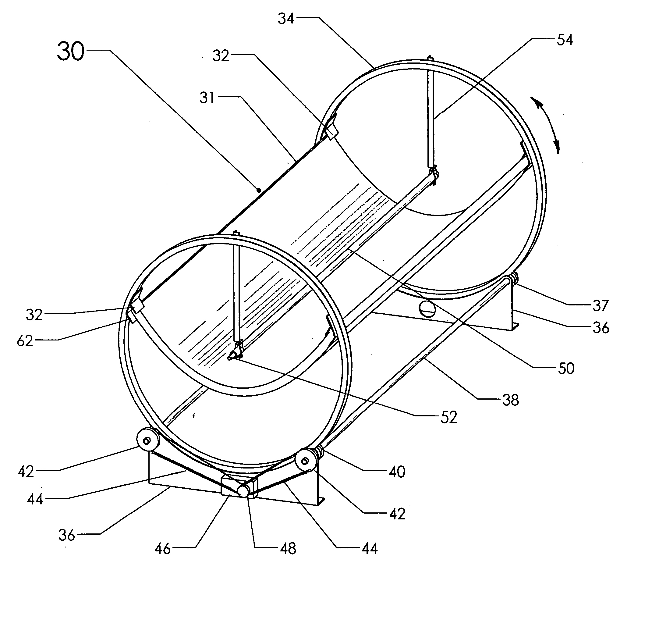
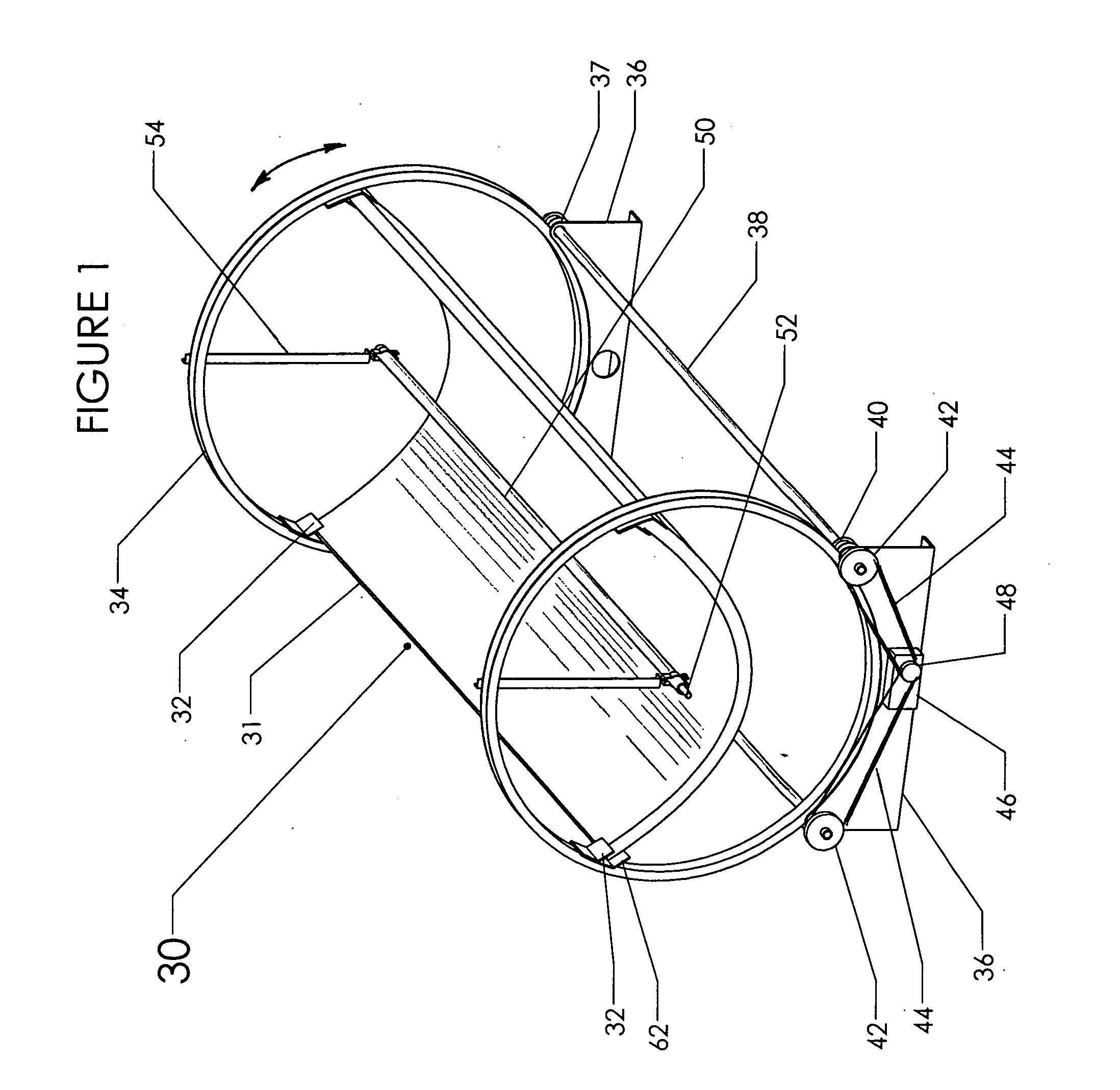
[0026]In accordance with one embodiment, a parabolic trough system is disclosed to capture solar heat. It has low mass, high rigidity and precise robust rotational control. The trough does not require massive supports, since it use a “sandwich structure” where the core is lightweight urethane foam and the skin is made of aluminum sheet. The inside skin also functions as the parabolic reflector. The shape minimizes wind loads by centering the receiver in the parabola and by making the center of focus the center of rotation.
[0027]The system can be rapidly built in the field since there are few parts. Assembly does not require heavy equipment. Support posts are used on both sides of the trough to minimize the anchoring requirements in wind loads.
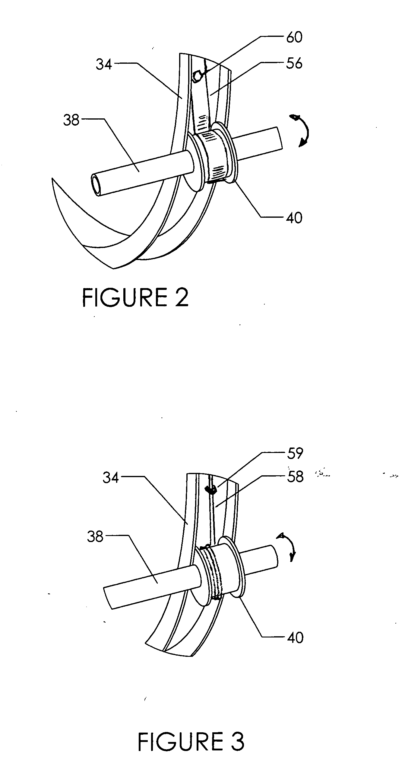
[0028]The trough bodies are rotated in a rotational control mechanism that uses circumscribing rings to support a continuous row of troughs that can sustain 120 mile per hour winds. Optical performance is improved with the drive ring design. The structure is continuous and torque is uniformly applied to each ring through two spools supported on drive tubes. A cable is wrapped around each spool as well as around the top part of the ring. As the spools rotate, they pull the cable and rotate the rings and troughs with precision and strength. The spools and cables also restrain the system under high wind loads.

Problems solved by technology

Previously parabolic troughs have been limited in torsion strength and as a result this impacts initial cost, optical accuracy, and maintenance costs.
Normal wind loads will deform the parabolic shape and affect how light reaches the focal point.
Inefficiencies occur when the light misses the receiver because of excess deformation.
If one end of the trough twists three degrees, the reflected light at this end will totally miss the receiver and render the device useless.
The extra material adds cost and limits the size of trough that can be built with this method.
These designs are costly due to the complex weld joints used to join the parabolic ribs to the main torque tube.
During most of the day, the drive and brake system must sustain a huge torque load from the weight of the trough being held in one position.
The drive and brake loads are magnified with the effect of wind and as a result these systems typically employ expensive hydraulic drives to hold and drive trough position.
One approach to help with the offset loading is to use counterweights for balance, but it still does not help with unbalanced wind loads which often exceed the weight of the structure.
Wind loads induce huge reaction loads at these support struts and they require massive concrete anchors to hold the system in position.
The corresponding anchor system is very expensive when supporting these large troughs.
If one drive fails or is not synchronous, it fractures the receiver pipe and leads to very high maintenance costs.
High cost of receiver breakage was a weakness discovered in the early SEGGS plants described by Price and Kearney in Parabolic-Trough Technology Roadmap: A Pathway for Sustained Commercial Development and Deployment of Parabolic-Trough Technology.
Since wind loads and gravity apply to the entire trough, there is a twisting moment across the face of each trough that causes optical error particularly at medium wind speeds of 15 to 30 miles per hour.
The most publicized SEGGS trough system in Daggett Calif. experiences high maintenance costs from this type of loading.
The glass reflectors are fragile and fracture when the trough structure is deformed from wind loads.
The sheet material in the above patents does not clarify detail about how the reflective material is supported and is thus prone to have permanent deformation at high wind loads.
If one trough is misaligned or the actuator fails, when the other units rotate, the receiver typically fractures and causes high heat losses and will sometimes start leaking forcing a shut-down of the entire system for repair.
Glass mirrors on troughs are very expensive as they must be formed to very precise parabolic geometry and they are also very fragile.
In this patent, it only operates under a protective structure and this limits its use.
The inflated housing is at risk from 80 mile per hour winds and from ultraviolet ray damage by the sun.
This error is the combined effect of tracking error, optical reflective error on the trough, wind deformation error, and the angular zone needed as the trough is stationary and tracking for a short segment of time.
Hydraulic units are ideal for large systems because they have high power and excellent precision, but they are costly.
Gear motor drives relying on gears or screw drives can be accurate but suffer as they do not have much power.
In that regard, high wind loads put a great deal of stress on spur gear or screw drive teeth.
Typically, the gear connected to the trough is large for improved accuracy, but being large also makes them very expensive like the ones shown on U.S. Pat. Nos. 257,560 by Ditzler (1882); 4,077,392 by Garner (1978); 4,515,148 by Boy-Marcotte et al.
This makes the teeth prone to high wear and deformation if they are overloaded.
This mandates the use of stepper or synchronous motors that are again more costly particularly when they must be designed for outdoor conditions.
They are known to have leakage issues and cause high maintenance costs.
Although they will have good rotational control with a large gear ratio between the drive and driven gears, they have not shown any provision to connect to the receiver.
Since the receiver is not designed to be in the center of rotation, it will rotate and translate and be very difficult to connect to a working plumbing system.
The associated hardware will be specialized, expensive, and difficult to maintain under the extreme operating temperatures and outdoor environmental conditions.
The trough can be rotated in one direction but lacks sufficient detail to describe how the trough is moved back to the original position.
As discussed earlier, the wind loads on a trough are enormous and unless concrete piers are employed, the system can not sustain typical 80 mile per hour winds.
There is concern that as cables stretch over time, some troughs will slip and not track the sun properly.
The spools and cables also restrain the system under high wind loads.

Method used


Image

  • Low Cost Fixed Focal Point Parabolic Trough
  • Low Cost Fixed Focal Point Parabolic Trough
  • Low Cost Fixed Focal Point Parabolic Trough

Examples


first embodiment

[0133]By referring to the drawings, the details and advantages of the present invention will be described. Reference numerals will be used during the description to indicate parts or portions of the present invention. Throughout these views, like reference characters will be used to designate like and corresponding parts in various views.

[0134]In order to keep the descriptions brief, alternative materials are not introduced, nor are alternative fabrication processes described. Anyone skilled in the art would know that steel components could be substituted for aluminum components and even for plastic parts. The descriptions given below describe embodiments that are cost effective at this time and not intended to communicate it will always be preferred. The sizes of the components are provided to clarify understanding and not intended to limit the scope of the invention.

[0135]Typically parabolic troughs are installed as a long row when multiple units are used. The system described bel...


PUM


Abstract

In accordance with one embodiment, a parabolic trough system is disclosed to capture solar heat. It has low mass, high rigidity and precise robust rotational control. The trough does not require massive supports, since it use a “sandwich structure” where the core is lightweight urethane foam and the skin is made of aluminum sheet. The inside skin also functions as the parabolic reflector. The shape minimizes wind loads by centering the receiver in the parabola and by making the center of focus the center of rotation.The system can be rapidly built in the field since there are few parts. Assembly does not require heavy equipment. Support posts are used on both sides of the trough to minimize the anchoring requirements in wind loads.The trough bodies are rotated in a rotational control mechanism that uses circumscribing rings to support a continuous row of troughs that can sustain 120 mile per hour winds. Optical performance is improved with the drive ring design. The structure is continuous and torque is uniformly applied to each ring through two spools supported on drive tubes. A cable is wrapped around each spool as well as around the top part of the ring. As the spools rotate, they pull the cable and rotate the rings and troughs with precision and strength. The spools and cables also restrain the system under high wind loads.

Description

CROSS-REFERENCE TO RELATED APPLICATIONS[0001]application Ser. No. 12 / 874,215 Filed Sep. 1, 2010[0002]Provisional Application 61 / 275,855 Filed Sep. 4, 2009OTHER PUBLICATIONS[0003]Parabolic-Trough Technology Roadmap: A Pathway for Sustained Commercial Development and Deployment of Parabolic-Trough Technology, January 1999 by Hank Price (National Renewable Energy Lab), and David Kearney (Kearney and Associates) Report No. NREL / TP-550-24748[0004]Sandwich Construction Solar Structural Facets Jan. 21, 1999, by Richard B Diver and James Grossman of Sandia National Laboratories Albuquerque, N. Mex. 87185FEDERALLY SPONSORED RESEARCH[0005]Not ApplicableSEQUENCE LISTING OR PROGRAM[0006]Not ApplicableBACKGROUND OF THE INVENTION[0007]1. Field of Invention[0008]This invention generally relates to parabolic troughs for concentrating solar energy along an axis, specifically a system of low cost parabolic troughs that can sustain high wind loads.[0009]2. Prior Art[0010]Previously parabolic troughs h...

Claims


Application Information

Patent Timeline
Patent Type & Authority Applications(United States)
IPC IPC(8): F24J2/12F16H19/08F24S23/71
CPCF16H19/005F24J2/1057F24J2/14F24J2/541Y10T74/18152F24J2002/5475Y02E10/45Y02E10/47F24J2/4636F24J2002/5458F24S23/74F24S23/82F24S30/425F24S40/80F24S2030/133F24S2030/14Y02E10/40
Inventor PERISHO, RANDAL JEROME
Owner PERISHO RANDAL JEROME
Learn More