Bipolar electrostatic chuck

a bipolar electrostatic and chuck technology, applied in the direction of electrostatic holding devices, basic electric elements, electric devices, etc., can solve the problems of difficult to completely cancel residual charges, complex structure of electrostatic chucks, and increased resistance of electrostatic chucks, so as to reduce residual charges, reduce residual charges, and minimize the number of charges remaining on the substrate attracting surface.

Active Publication Date: 2011-05-05
CREATIVE TECH CORP
View PDF3 Cites 19 Cited by
  • Summary
  • Abstract
  • Description
  • Claims
  • Application Information

AI Technical Summary

Benefits of technology

[0024]According to the present invention, charges generated on the substrate attracting surface when a voltage is applied to the electrodes can be canceled efficiently with charges of the opposite polarity existing in the periphery. Therefore, residual charges can be canceled promptly when the voltage application is stopped. In addition, according to the electrode shape of the present invention, electric flux lines generated by the voltage application can stay in the vicinity of the substrate attracting surface. Therefore, an amount of attracted charged particles such as ions and electrons can be suppressed, with a result that the number of charges remaining on the substrate attracting surface can be minimized. For this reason, the bipolar electrostatic chuck of the present invention can reduce the residual charges promptly after the voltage application is stopped. In addition, the bipolar electrostatic chuck is also excellent in the substrate attracting / holding performance when a voltage is applied. In addition, it is possible to control the formation of the electric flux lines to be at the vicinity of the substrate attracting surface, with a result that amount of attracted charged particles floating around the electrostatic chuck can be reduced.

Problems solved by technology

Therefore, there is a problem that charged particles such as ions and electrons that are used for processing of the substrate may be attracted by the upper insulating layer so as to generate residual charges, which maintains the substrate in the attracted state even after a long period from power-off.
In addition, there is also a problem that charged and floating particles around the electrostatic chuck may be attracted.
However, in recent years, a structure of the electrostatic chuck is apt to be complicated because of necessities of improving attraction force of the electrostatic chuck or processing substrates of increasing size.
For this reason, it is difficult to cancel the residual charges completely by leading the charges to flow to the earth or by supplying charges having the opposite polarity.
However, as described above, in recent years, an electrode having a complicated shape such as a comb-shaped electrode is studied for improving the attraction force, and hence it is actually difficult to adopt the above-mentioned method for such electrode.
The control or the like is very difficult.

Method used


Image

  • Bipolar electrostatic chuck
  • Bipolar electrostatic chuck
  • Bipolar electrostatic chuck

Examples


example 1

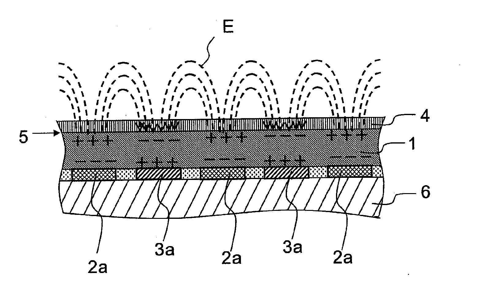
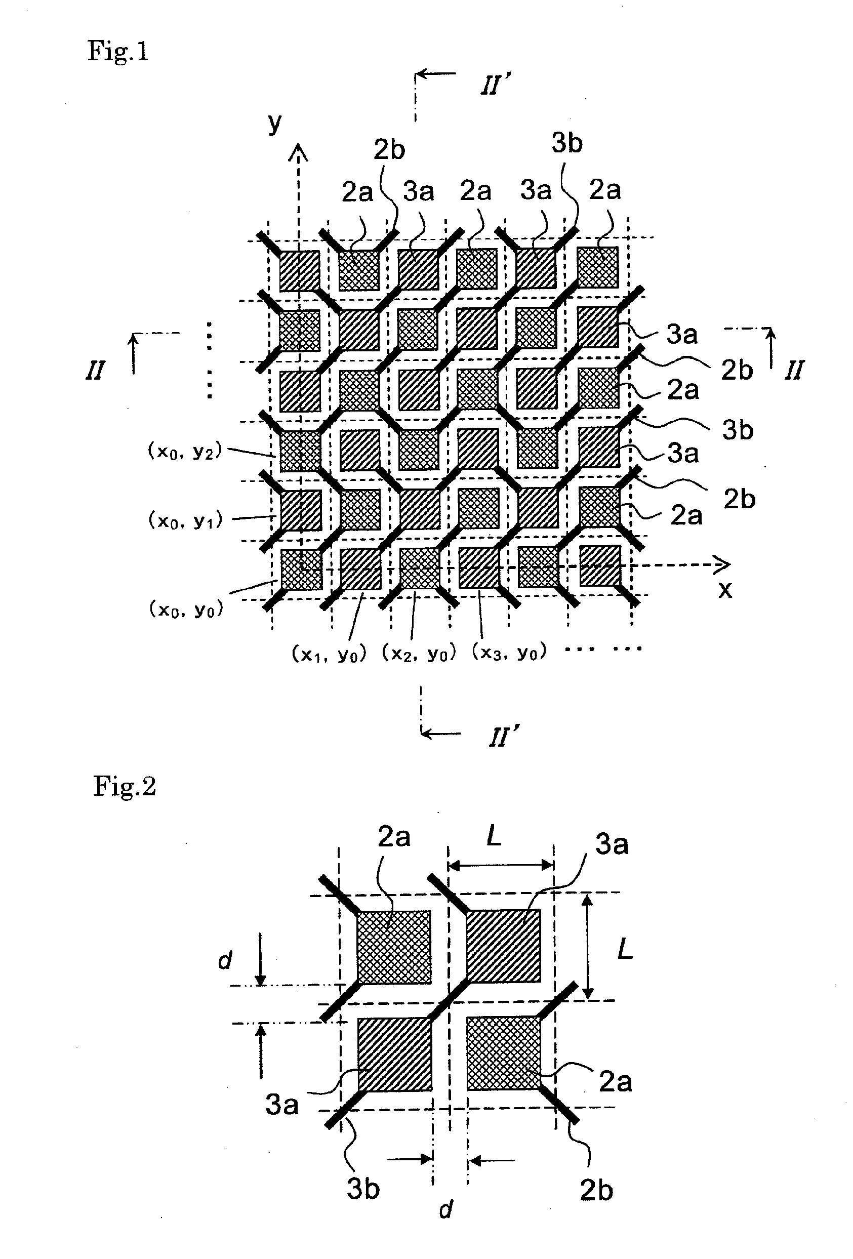
[0032]A polyimide sheet (Kapton-H manufactured by DuPont-Toray Co., Ltd. having a thickness of 125 μm) having a diameter of 298 mm was prepared as a lower insulating layer 6, and a chrome layer having a thickness of 0.1 μm was formed on the surface thereof to make a smooth surface by processing the surface in advance by the ion plating method. Next, an electrode layer made of copper having a diameter of 296 mm and a thickness of 0.5 μm was formed on the chrome layer of the polyimide sheet by the ion plating method, and a first electrode 2 and a second electrode 3 as illustrated in FIGS. 1 and 2 were obtained by etching using nitrate etchant. Here, a virtual cell width L was set to 5 mm, and first electrode sections 2a and second electrode sections 3a each have dimensions of 4.5 mm×4.5 mm. The first electrode sections 2a and the second electrode sections 3a were arranged in cells alternately in a x direction and in a y direction, and a space d between neighboring electrode sections w...

example 2

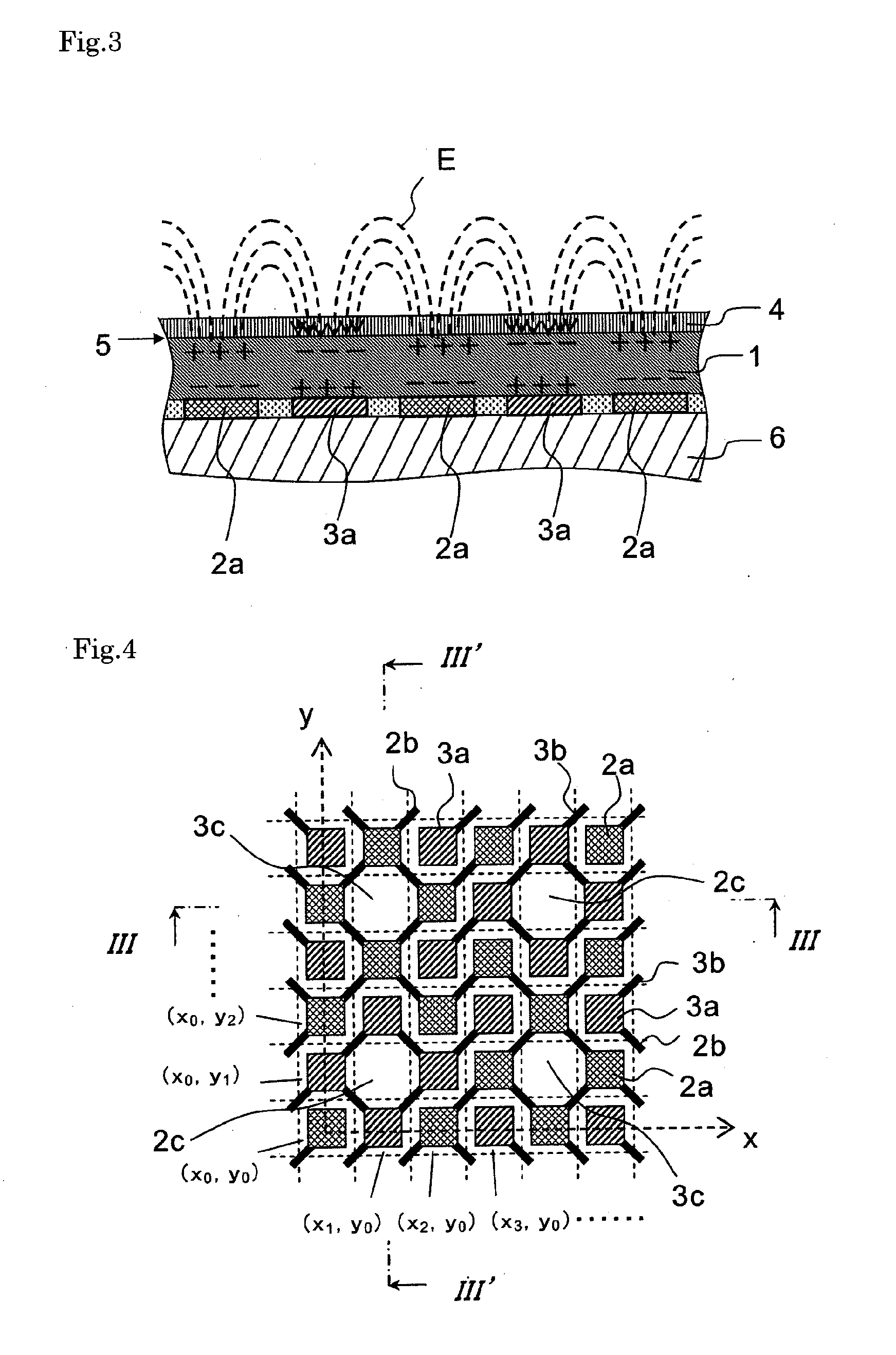
[0035]As to the first electrode 2 and the second electrode 3 forming the electrode layer, as illustrated in FIG. 4, electrode sections of apex portions of 4×4 virtual cells were eliminated, with a result that the number of electrodeless portions 2c in which the first electrode section 2a was missing was the same as the number of electrodeless portions 3c in which the second electrode section 3a was missing on the surface of the electrode layer. Other structure was the same as in example 1 for obtaining the electrode sheet. Next, the surface of the upper insulating layer 1 was covered with a mask, and etching was performed by using alkali etchant only for polyimide (product name: polyimide etchant manufactured by Mitsubishi Paper Mills Ltd.), so as to eliminate the polyimide sheet except for places corresponding to the virtual cells of the electrodeless portions 2c and 3c by a depth of 10 μm (corresponding to insulating layer recess 1c). Thus, insulating layer tops 1a having a size o...


PUM


Abstract

Provided is a bipolar electrostatic chuck, which has excellent substrate attracting/holding performance when a voltage is applied, and excellent residual charges reducing performance when voltage application is stopped. The bipolar electrostatic chuck includes at least an electrode layer including a first electrode and a second electrode, and an upper insulating layer which forms a substrate attracting surface for attracting a substrate. In a case where a surface of the electrode layer is regarded to be divided into a plurality of virtual cells having a predetermined width (L) in an x direction and a y direction, first electrode sections forming the first electrode and second electrode sections forming the second electrode are alternately arranged in the plurality of virtual cells in the x direction, and are alternately arranged in the plurality of virtual cells in the y direction.

Description

TECHNICAL FIELD[0001]The present invention relates to a bipolar electrostatic chuck, and more specifically, to a bipolar electrostatic chuck which has excellent substrate attracting / holding performance when a voltage is applied, and is capable of canceling residual charges promptly when voltage application is stopped.BACKGROUND ART[0002]An electrostatic chuck is used for attracting and holding a semiconductor substrate in various apparatuses such as an ion implantation apparatus, an ion doping apparatus, and a plasma immersion in a semiconductor manufacturing process, an exposing apparatus using an electron beam or an extreme ultraviolet (EUV) lithography, or a wafer inspection apparatus for silicon wafers or the like. In addition, in a field of manufacturing liquid crystal displays, the electrostatic chuck is used for attracting and holding an insulating substrate in a substrate combining apparatus, which is used for filling liquid crystal between glass substrates, or in an ion dop...

Claims


Application Information

Patent Timeline
Patent Type & Authority Applications(United States)
IPC IPC(8): H01L21/683
CPCH02N13/00H01L21/6833H01L21/6831
Inventor FUJISAWA, HIROSHITATSUMI, YOSHIAKI
Owner CREATIVE TECH CORP
Why Eureka
Try Eureka