
Isolated switching power supply apparatus

a power supply apparatus and isolation technology, applied in the direction of electric variable regulation, process and machine control, instruments, etc., can solve the problems of increasing the size of the output ripple, and increasing the size of the smoothing capacitor cb>3/b>, so as to reduce the number of components, reduce the scale of the circuit, and reduce the effect of switching loss

Active Publication Date: 2011-05-05
MURATA MFG CO LTD
View PDF12 Cites 22 Cited by
  • Summary
  • Abstract
  • Description
  • Claims
  • Application Information

AI Technical Summary

Benefits of technology

[0015]Preferred embodiments of the present invention solve the above-described problems and provide an isolated switching power supply apparatus which allows energy to be transmitted from the primary side to the secondary side of a transformer irrespective of the on / off periods of a switching device, which can suppress generation of switching noise that is generated during on / off switching periods and reduce an output ripple, and which allows a low-voltage switching device to be used.

Problems solved by technology

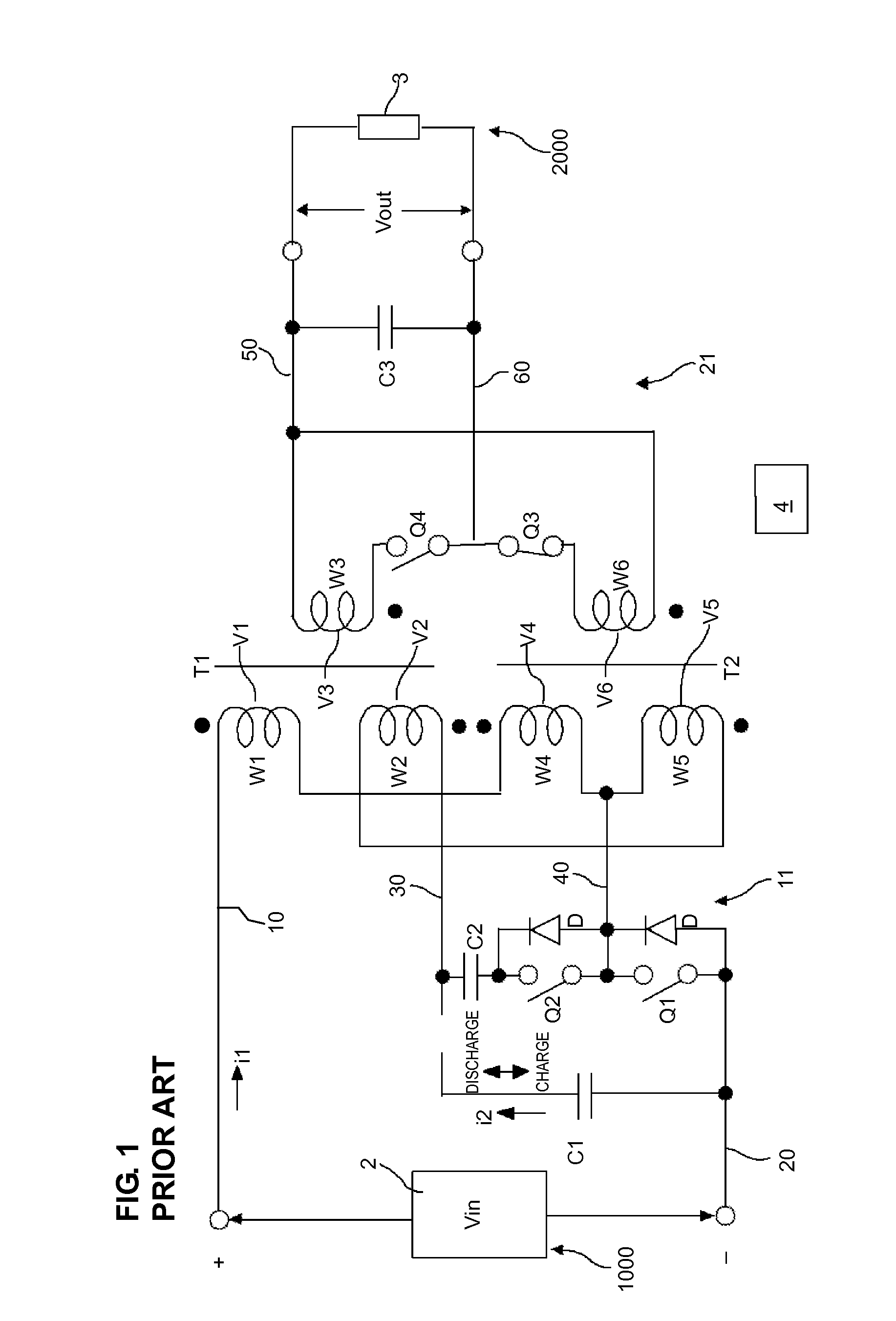
However, the isolated switching power supply apparatus disclosed in Japanese Unexamined Patent Application Publication No. 2005-51994 is characterized in that a choke coil is not required as a result of two transformers having been provided, and hence, has a problem in that two transformers are needed, resulting in an increased size of the circuit.
In addition, although the advantage of no choke coil is necessary for allowing energy to be transmitted from the primary side to the secondary side both when the main switch Q1 is on and off is effective, there is a problem in that no choke coil on the secondary side causes an output ripple to increase due to switching noise generated during the on / off switching period of the main switching device Q1 on the primary side, resulting in an increased size of the smoothing capacitor C3.
A high-voltage switching device has a large on resistance, which is a resistance component during conduction, and hence, conduction loss in the switching device increases.
This results in a decrease in efficiency and an increase in cost.

Method used


Image

  • Isolated switching power supply apparatus
  • Isolated switching power supply apparatus
  • Isolated switching power supply apparatus

Examples


first preferred embodiment

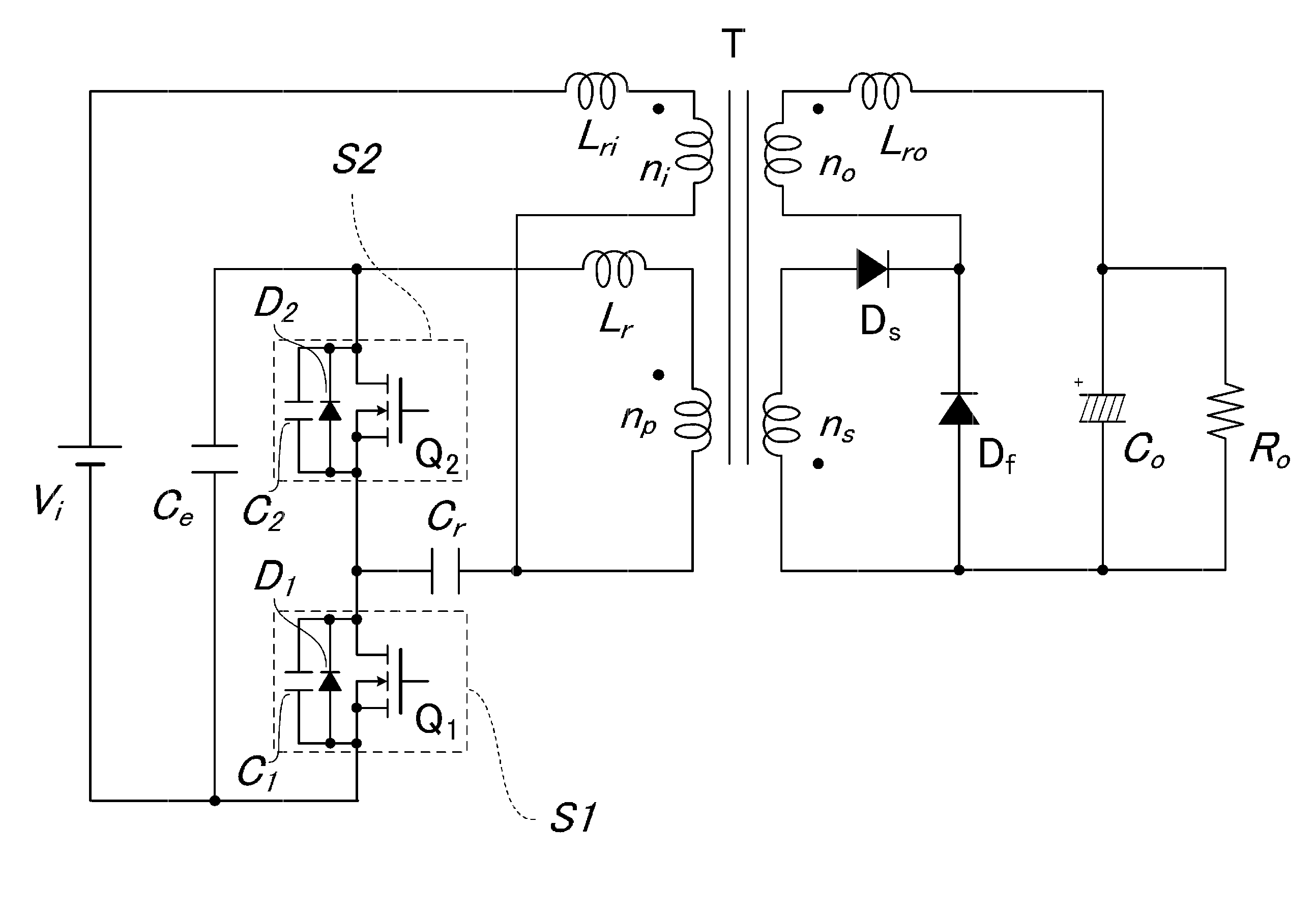
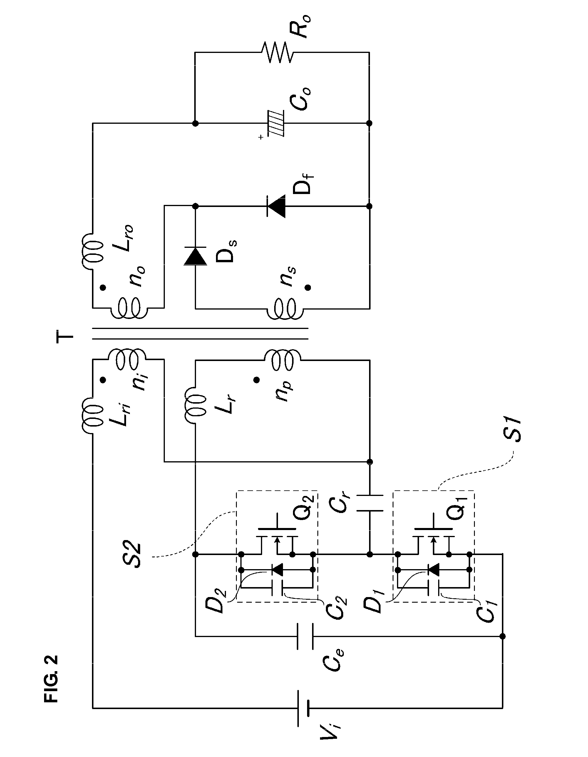
[0075]FIG. 2 is a circuit diagram of an isolated switching power supply apparatus according to a first preferred embodiment of the present invention.

[0076]Referring to FIG. 2, in this isolated switching power supply apparatus, a series circuit including a first inductor Lri, a second primary winding ni of a composite transformer T, a third capacitor Cr, and a first switch circuit S1 is connected between the + terminal and the − terminal of a power input portion to which a DC voltage V1 is applied. A series circuit including a first primary winding np of the composite transformer T, a second inductor Lr, and a fourth capacitor Ce is connected between the connection node of the second primary winding ni of the composite transformer T and the third capacitor Cr and the − terminal of the power input portion. A second switch circuit S2 is connected between the connection node of the third capacitor Cr and the first switch circuit S1 and the connection node of the second inductor Lr and t...

second preferred embodiment

[0118]FIG. 3 is a circuit diagram of an isolated switching power supply apparatus according to a second preferred embodiment. The difference from the circuit illustrated in FIG. 2 is the position where the third diode Ds is connected. That is, in FIG. 3, the anode of the fourth diode Df is connected to the anode of the fourth diode Df. The other portions of the configuration are the same as those illustrated in FIG. 2.

[0119]This configuration also provides advantages similar to those of the first preferred embodiment of the present invention.

[0120]The advantages provided by the configuration of the isolated switching power supply apparatus according to the second preferred embodiment are, among the advantages achieved by the first preferred embodiment of the present invention described above.

third preferred embodiment

[0121]FIG. 4 is a circuit diagram of an isolated switching power supply apparatus according to a third preferred embodiment. The differences from the circuit illustrated in FIG. 2 are that the first primary winding np and the first secondary winding ns operate as a forward system and the second primary winding ni and the second secondary winding no operate as a flyback system. In other words, referring to FIG. 4, while the first switching device Q1 is on and the second switching device Q2 is off, a voltage is induced in the first secondary winding ns, whereby the third diode Ds is turned on and a DC current is made to flow through the third inductor Lro, and a DC output voltage is applied to the load Ro.

[0122]While the first switching device Q1 is off and the second switching device Q2 is on, a voltage is induced in the second secondary winding no, whereby the fourth diode Df is turned on and a DC current is made to flow through the third inductor Lro, and a DC output voltage is app...


PUM


Abstract

In an isolated switching power supply apparatus, by performing on / off control of a first switching device and a second switching device, energy is transmitted from the primary side to the secondary side using a second primary winding and a second secondary winding while the first switching device is on, and energy is transmitted by a first primary winding and a first secondary winding while the second switching device is on. The first secondary winding and the second secondary winding are connected in series with one another, and an inductor is inserted in series to the second secondary winding. An output current is made to flow through the inductor irrespective of whether the first switching device is on or the second switching device is on.

Description

BACKGROUND OF THE INVENTION[0001]1. Field of the Invention[0002]The present invention relates to an isolated switching power supply apparatus in which there is substantially no period during which energy transmission between the primary side and secondary side of a transformer is not performed.[0003]2. Description of the Related Art[0004]To date, known examples of general isolated switching power supply apparatuses include forward converters and flyback converters. All of these isolated switching power supply apparatuses store energy in a transformer or an inductor while the main switching device is on, and thereby transmit energy from the primary side to the secondary side while the primary side main switch is either on or off. Hence, there exists a period during which energy is not transmitted from the primary side to the secondary side while the main switch is either off or on.[0005]A known example of an isolated switching power supply apparatus in which energy is transmitted fro...

Claims


Application Information

Patent Timeline
Patent Type & Authority Applications(United States)
IPC IPC(8): H02M3/335
CPCH01F3/10H02M3/33569H01F27/40H01F27/38H02M3/33571H02M3/01
Inventor HOSOTANI, TATSUYA
Owner MURATA MFG CO LTD
Learn More