Disperser arrangement for a spray dryer absorber

a technology of spray dryer and absorber, which is applied in the direction of combustible gas purification/modification, lighting and heating apparatus, separation processes, etc., can solve the problems of high rpm of the atomizer wheel, the inability to increase the capacity of a single spray dryer absorber with respect to the flue gas flow rate, and the inability to meet the requirements of a single spray dryer

Inactive Publication Date: 2011-05-12
ALSTOM TECH LTD
View PDF4 Cites 6 Cited by
  • Summary
  • Abstract
  • Description
  • Claims
  • Application Information

AI Technical Summary

Benefits of technology

[0008]An object of the present invention is to provide a spray dryer absorber in which the fo

Problems solved by technology

A problem of the spray dryer absorber of U.S. Pat. No. 4,755,366 is that it is difficult to increase the capacity of a single spray dryer absorber with respect to the flue gas flow rate.
One reason for this difficulty is that the very high rpm of the atomizer wheel poses mechanical obstacles to up-scaling its size.
It is noted in U.S. Pat. No. 4,519,99

Method used


Image

  • Disperser arrangement for a spray dryer absorber
  • Disperser arrangement for a spray dryer absorber
  • Disperser arrangement for a spray dryer absorber

Examples


Embodiment Construction

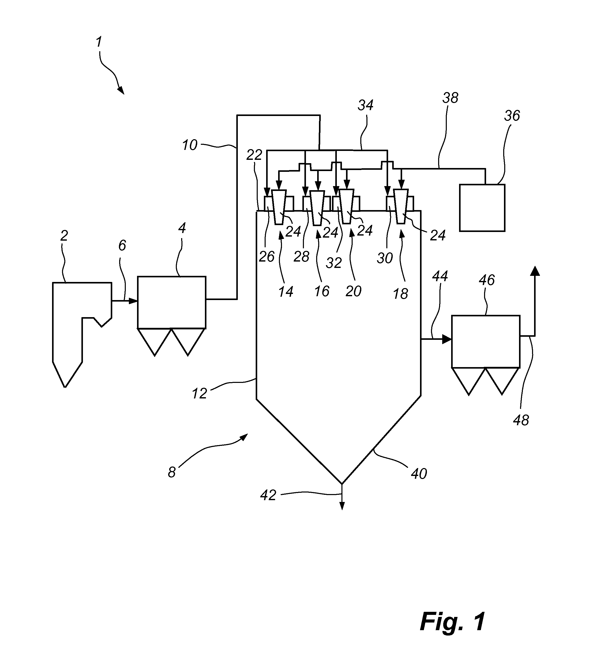
[0026]FIG. 1 is a schematic side view and illustrates a power plant 1. The power plant 1 comprises a boiler 2 in which a fuel, such as coal or oil, is combusted. The combustion of the fuel generates a hot process gas in the form of a flue gas. Sulphur species contained in the coal or oil will form sulphur dioxide, which will form part of the flue gas. The flue gas is forwarded from the boiler 2 to an electrostatic precipitator 4 via a duct 6. The electrostatic precipitator 4, an example of which is described in U.S. Pat. No. 4,502,872, serves to remove dust particles from the flue gas.

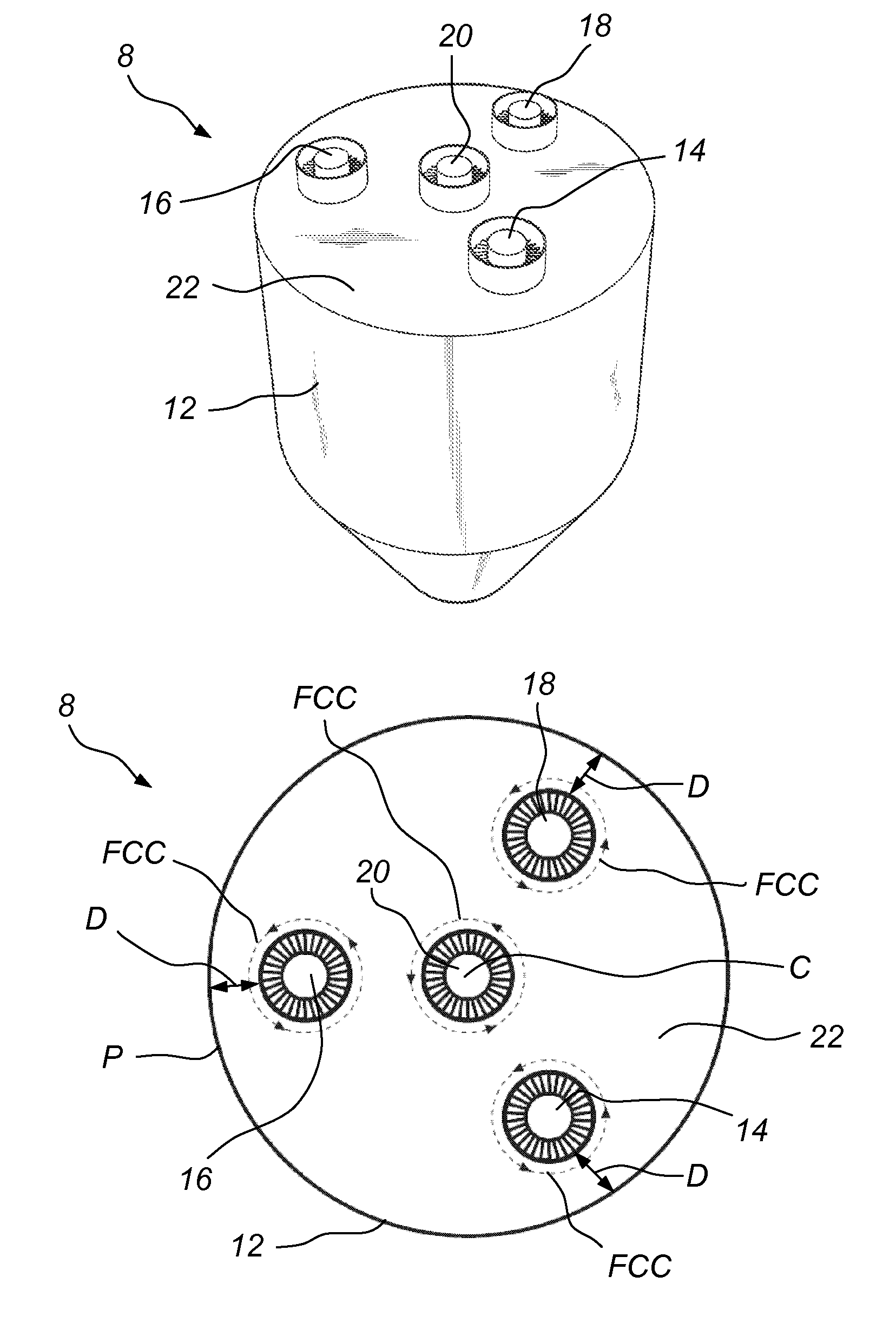
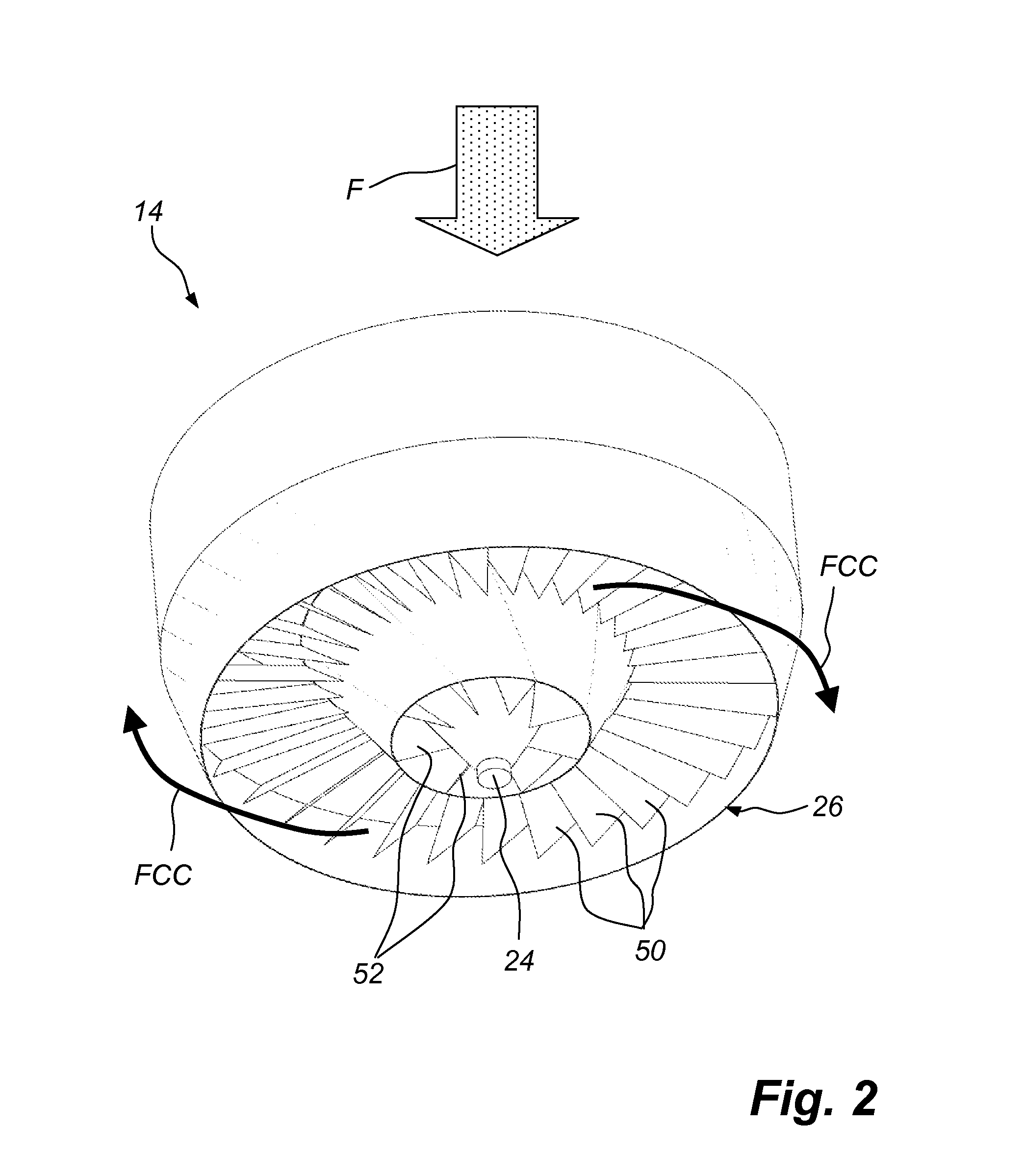
[0027]The flue gas, from which most of the dust particles have been removed, is forwarded to a spray dryer absorber 8 via a duct 10. The spray dryer absorber 8 comprises a spray dryer chamber 12 and four dispersers 14, 16, 18, 20 that are mounted at a roof 22 of the spray dryer chamber 12. Each disperser 14, 16, 18, 20 comprises an atomizer 24. The atomizers 24 could be of the so-called rotary atomizer...


PUM

PropertyMeasurementUnit
Distanceaaaaaaaaaa

Abstract

A spray dryer absorber (8) is operative for removing gaseous pollutants from a hot process gas and comprises a spray dryer chamber (12) and a plurality of dispersers (14, 16, 18, 20) mounted at a roof (22) of the spray dryer chamber (12), each such disperser (14, 16, 18, 20) being operative for dispersing a portion of the hot process gas around a respective atomizer (24). Said plurality of dispersers (14, 16, 18, 20) comprises a central disperser (20), which is located at the centre (C) of the roof (22) of the spray dryer chamber (12), and at least 3 peripheral dispersers (14, 16, 18) surrounding the central disperser (20), each of said peripheral dispersers (14, 16, 18) being located at substantially the same distance (D) from the periphery (P) of the spray dryer chamber (12).

Description

FIELD OF THE INVENTION[0001]The present invention relates to a spray dryer absorber which is operative for removing gaseous pollutants from a hot process gas and comprises a spray dryer chamber and a plurality of dispersers mounted at a roof of the spray dryer chamber, each such disperser being operative for dispersing a portion of the hot process gas around a respective atomizer which is operative for atomizing an absorption liquid, each disperser being provided with a flow directing device, which is operative for providing the respective portion of the hot process gas with a rotary movement around the atomizer, as seen from the top of the spray dryer chamber.[0002]The present invention further relates to a method of removing gaseous pollutants from a hot process gas by means of a spray dryer absorber.BACKGROUND OF THE INVENTION[0003]In the combustion of a fuel, such as coal, oil, peat, waste, etc., in a combustion plant, such as a power plant, a hot process gas is generated, such ...

Claims


Application Information

Patent Timeline
IPC IPC(8): B01D53/14
CPCB01D53/1456B01D53/185B01D53/505F23J2219/60B01D2257/302F23J15/02F23J2217/102B01D53/78B01D53/18B01D53/50
Inventor HMAN, STEFANJOHANSSON, LARS-ERIKRAFIDI, NABILTABIKH, ALITRYGGESON, HENRIK
Owner ALSTOM TECH LTD
Why Eureka
Try Eureka