System for recovering carbon dioxide from flue gas

a carbon dioxide and flue gas technology, applied in indirect heat exchangers, lighting and heating apparatus, separation processes, etc., can solve the problems of large shell diameter, long residence time, and inability to recover carbon dioxide, so as to reduce the decomposition of absorbents, reduce the installation area of facilities, and reduce the effect of amine solution decomposition

Active Publication Date: 2011-05-12
MITSUBISHI HEAVY IND ENG LTD
View PDF15 Cites 25 Cited by
  • Summary
  • Abstract
  • Description
  • Claims
  • Application Information

AI Technical Summary

Benefits of technology

[0049]According to the present invention, because regenerated CO2 absorbent is reheated by a falling film reboiler, decomposition of the absorbent is reduced, and because the reboiler is made compact, an installation area of facilities can be made small. Further, because piping also becomes simple, installation thereof can be facilitated.
[0050]Further, because there is no boiling point rise within the reboiler, the pressure can be increased by 30 kilopascals than in conventional thermo-siphon reboilers, thereby enabling to reduce the power of a CO2 compressor.

Problems solved by technology

However, it has a problem that evaporated vapor and liquid become mixed phase gas-liquid two phase flow 1034 to pass through the heat exchanger and an outlet piping, thereby increasing flow resistance.
As a result, thermal decomposition of the amine solution therein becomes a problem.
The boiling point rise for this is approximately from 0.2 to 1° C. However, a very large shell diameter is required for vapor-liquid separation and a residence time thereof becomes long.

Method used


Image

  • System for recovering carbon dioxide from flue gas
  • System for recovering carbon dioxide from flue gas
  • System for recovering carbon dioxide from flue gas

Examples


embodiment

[0071]A system for recovering carbon dioxide from flue gas according to an embodiment of the present invention is explained with reference to the drawings.

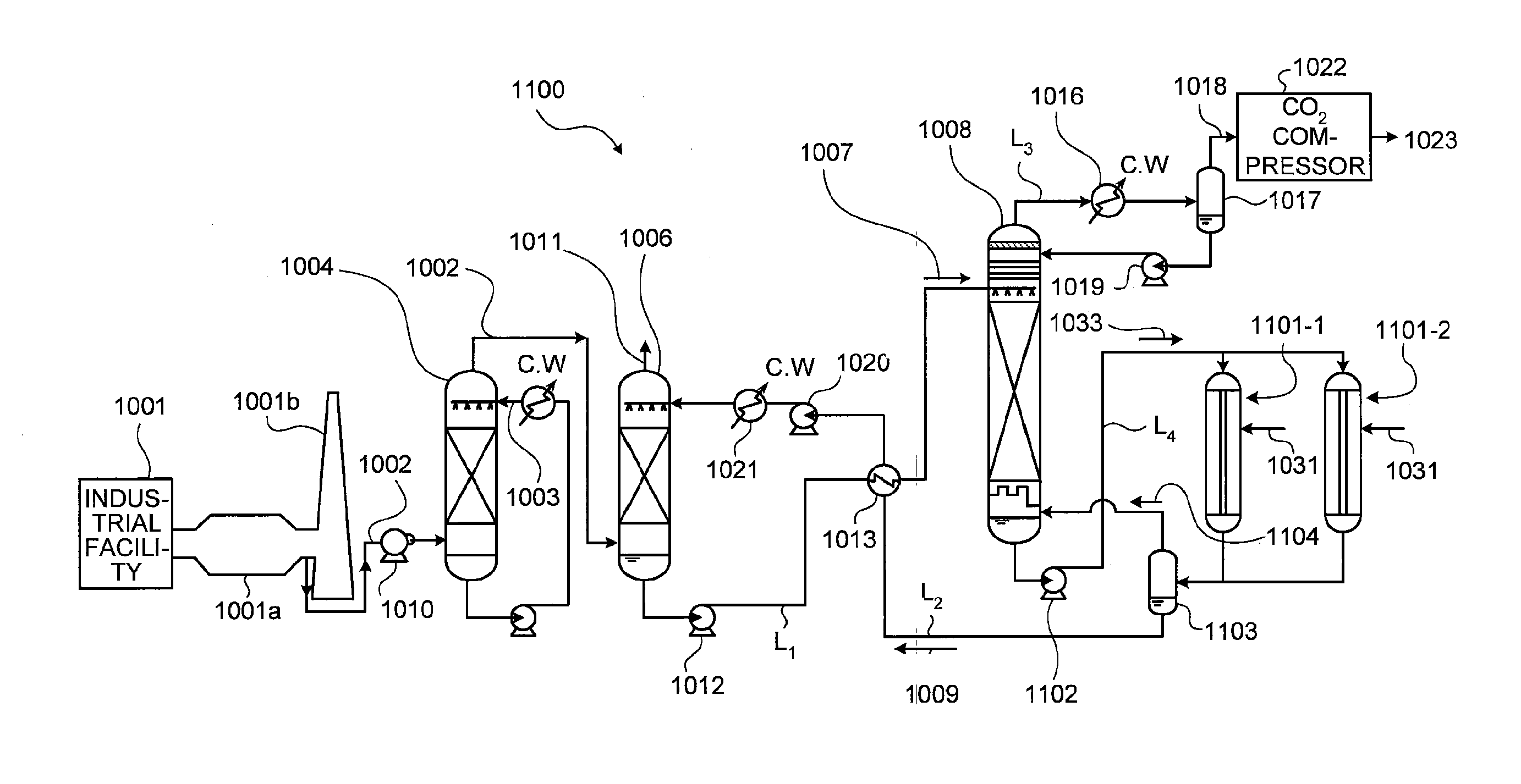
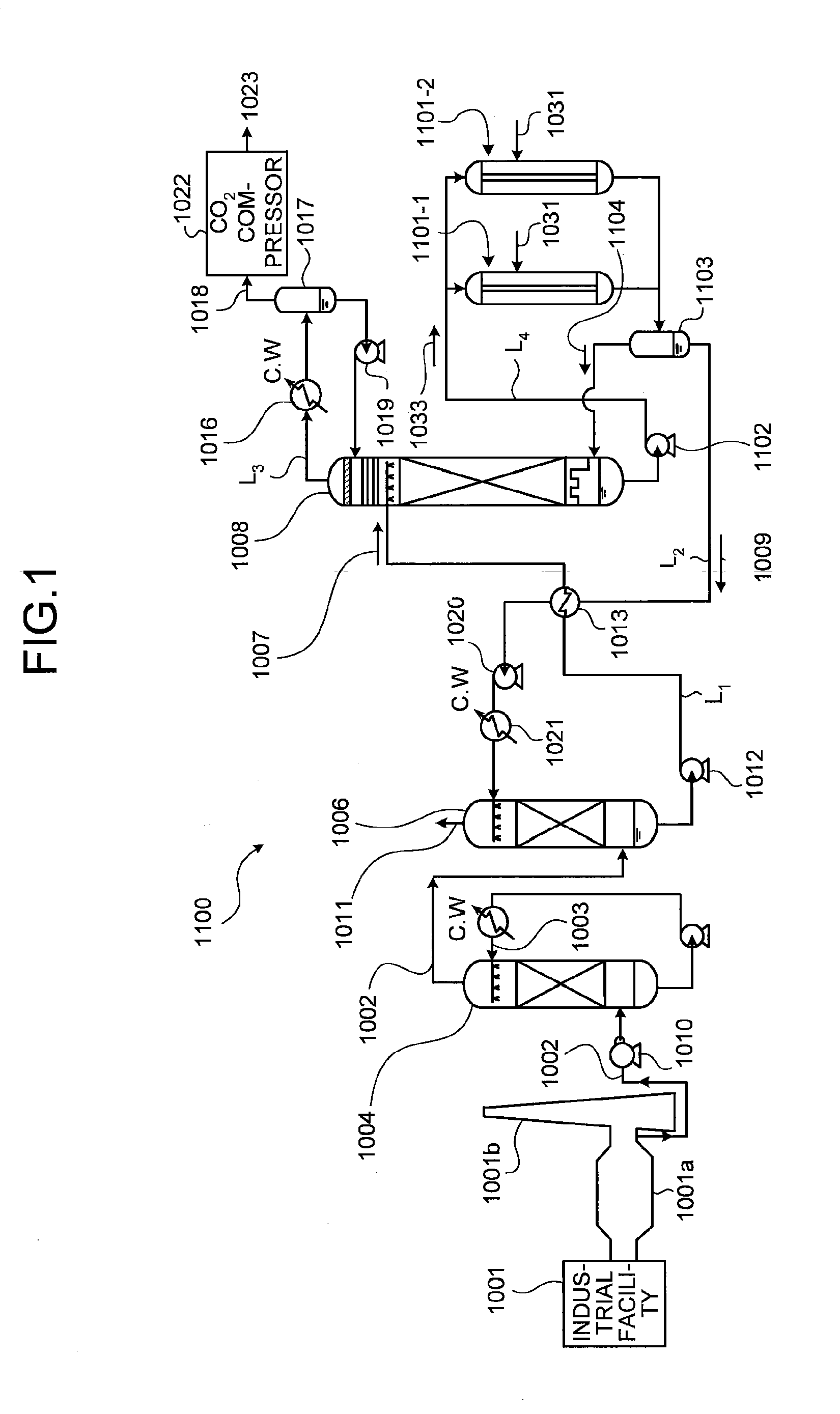
[0072]FIG. 1 is a schematic diagram of the system for recovering carbon dioxide from flue gas according to the present embodiment.

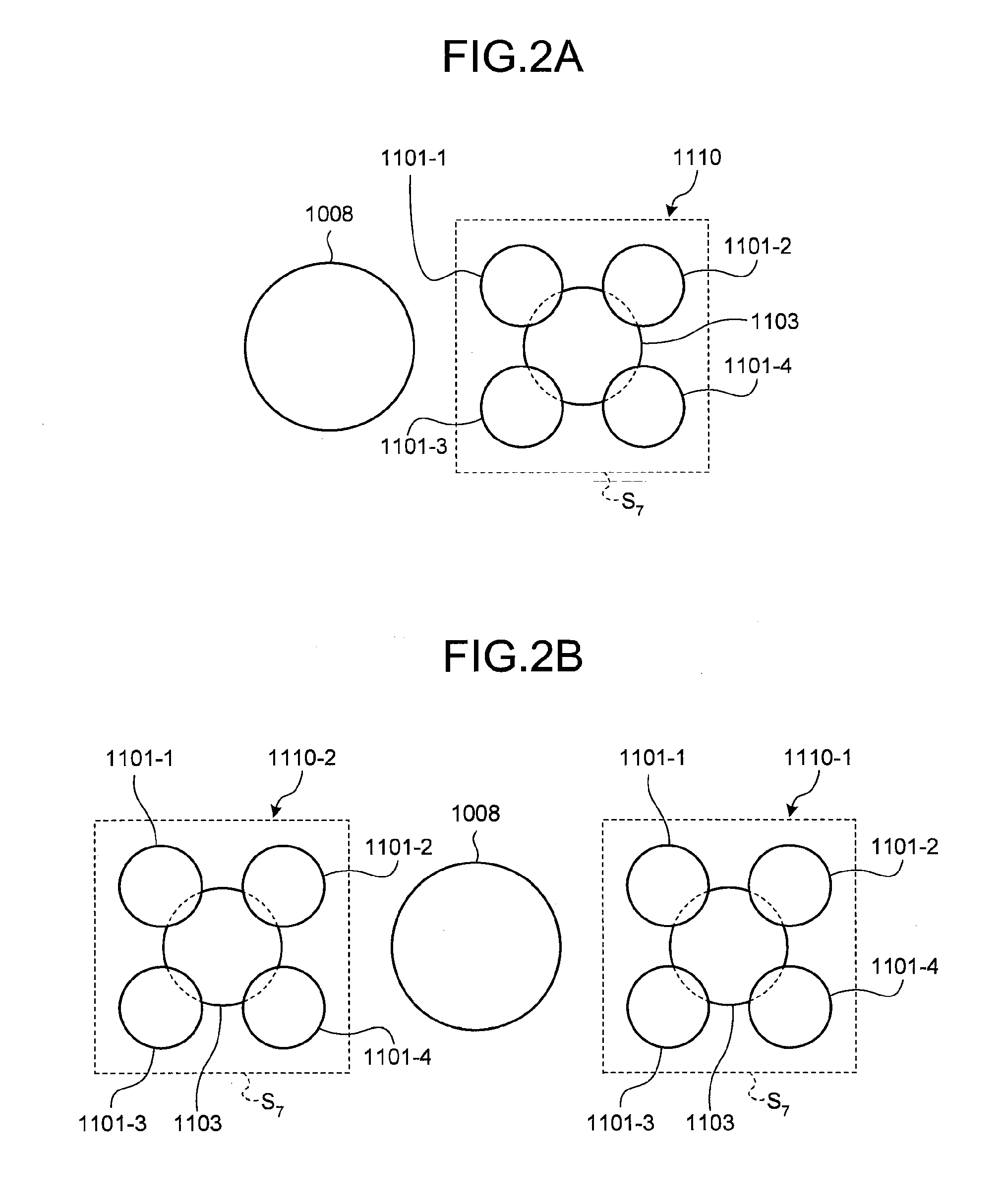
[0073]As shown in FIG. 1, a system for recovering carbon dioxide from flue gas 1100 according to the present embodiment includes the absorber 1006 that brings CO2 absorbent that absorbs CO2 contained in the flue gas 1002 exhausted from industrial facilities 1001 into contact with the flue gas 1002 to remove CO2 from the flue gas 1002, the regenerator 1008 that strips CO2 from CO2 absorbent (rich solution) 1007, which is fed from the absorber 1006 through a first feed line L1 and has absorbed CO2, to regenerate CO2 absorbent, thereby acquiring the regenerated CO2 absorbent (lean solution) 1009, two or more falling film reboilers 1101-1 and 1101-2 that draw off regenerated CO2 absorbent (amine solution) 1...


PUM

PropertyMeasurementUnit
pressureaaaaaaaaaa
boiling pointaaaaaaaaaa

Abstract

To include an absorber (1006) that brings CO2 absorbent that absorbs CO2 contained in flue gas (1002) into contact with the flue gas to remove CO2 from the flue gas, a regenerator (1008) that strips CO2 from CO2 absorbent (rich solution), which is fed from the absorber through a first feed line L1 and has absorbed CO2, to regenerate CO2 absorbent, thereby acquiring regenerated CO2 absorbent (lean solution) (1009), falling film reboilers (1101-1 and 1101-2) that draw off CO2 absorbent (amine solution) (1033) from near the bottom of the regenerator and reheats regenerated CO2 absorbent via steam (1031), a first liquid-vapor separator (1103) that separates the CO2 absorbent reheated by the falling film reboilers into regenerated CO2 absorbent in which CO2 has been removed and vapor containing CO2, and a second feed line L2 for supplying the separated regenerated CO2 absorbent to the absorber.

Description

TECHNICAL FIELD[0001]The present invention relates to a system for recovering carbon dioxide from flue gas, in which a reboiler of a regenerator can be compactly installed, thermal decomposition of amine solution become small, and power of a CO2 compressor can be reduced.BACKGROUND ART[0002]Greenhouse effect due to CO2 has been pointed out as a cause of global warming in recent years, and a measure against it has become an urgent issue internationally for protecting the global environment. Generation sources of CO2 include all sorts of human activity areas that burn fossil fuel, and demands for the reduction of discharge thereof are further increasing. Accompanying this trend, a method of removing and recovering CO2 in combustion flue gas by bringing combustion flue gas in a boiler into contact with amine CO2 absorbent, and a method of storing recovered CO2 without discharging it to the air have been strenuously researched, with regard to power generation facilities such as a therma...

Claims


Application Information

Patent Timeline
Patent Type & Authority Applications(United States)
IPC IPC(8): B01D53/18B01D53/62C01B32/50
CPCB01D53/1418B01D53/1425B01D53/1475B01D2251/80B01D2252/20405Y02C10/06B01D2252/20484B01D2258/0283F28D3/02Y02C10/04B01D2252/20421Y02C20/40
Inventor INOUE, KATSUFUMIKAMIJO, TAKASHIOISHI, TSUYOSHIYONEKAWA, TAKAHITOTANAKA, HIROSHI
Owner MITSUBISHI HEAVY IND ENG LTD
Why Eureka
Try Eureka