Electromechanical transducer and method of manufacturing the same

a transducer and electromechanical technology, applied in the direction of influencing generators, mechanical vibration separation, line/current collector details, etc., can solve problems such as dielectric breakdown

Inactive Publication Date: 2011-05-19
CANON KK
View PDF4 Cites 69 Cited by
  • Summary
  • Abstract
  • Description
  • Claims
  • Application Information

AI Technical Summary

Benefits of technology

[0009]According to the present invention, the outer frame connection portion functions as a sealing material of a space that contains the grooves, whereby the grooves provided for device separation can be sealed while allowing the interior of each groove to remain an unclogged space, and foreign matter can be prevented from falling into the grooves.

Problems solved by technology

On the other hand, a CMUT in which the groove is left as an unclogged space has the risk of foreign matter falling into the groove and causing dielectric breakdown.

Method used


Image

  • Electromechanical transducer and method of manufacturing the same
  • Electromechanical transducer and method of manufacturing the same
  • Electromechanical transducer and method of manufacturing the same

Examples


first embodiment

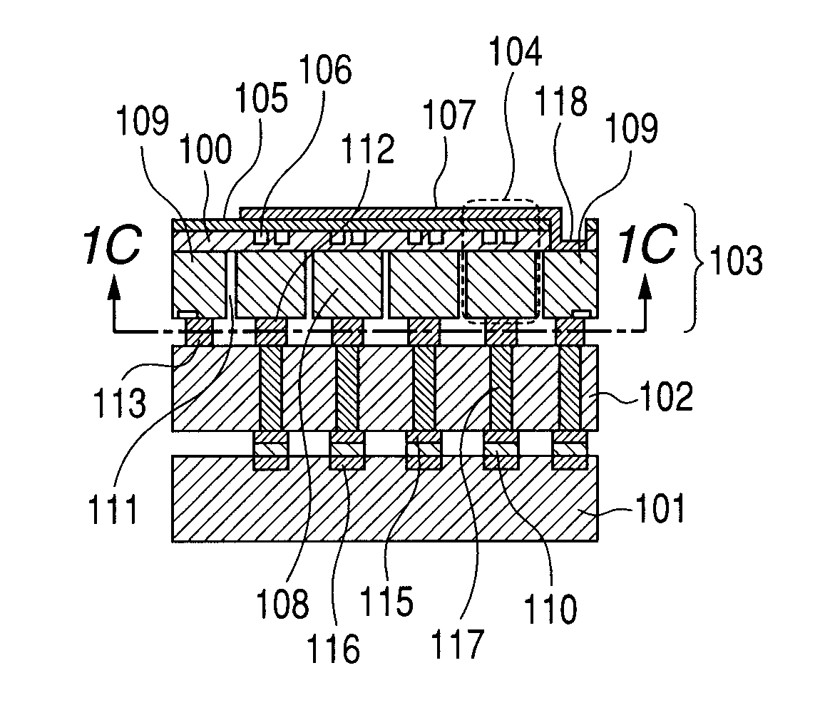
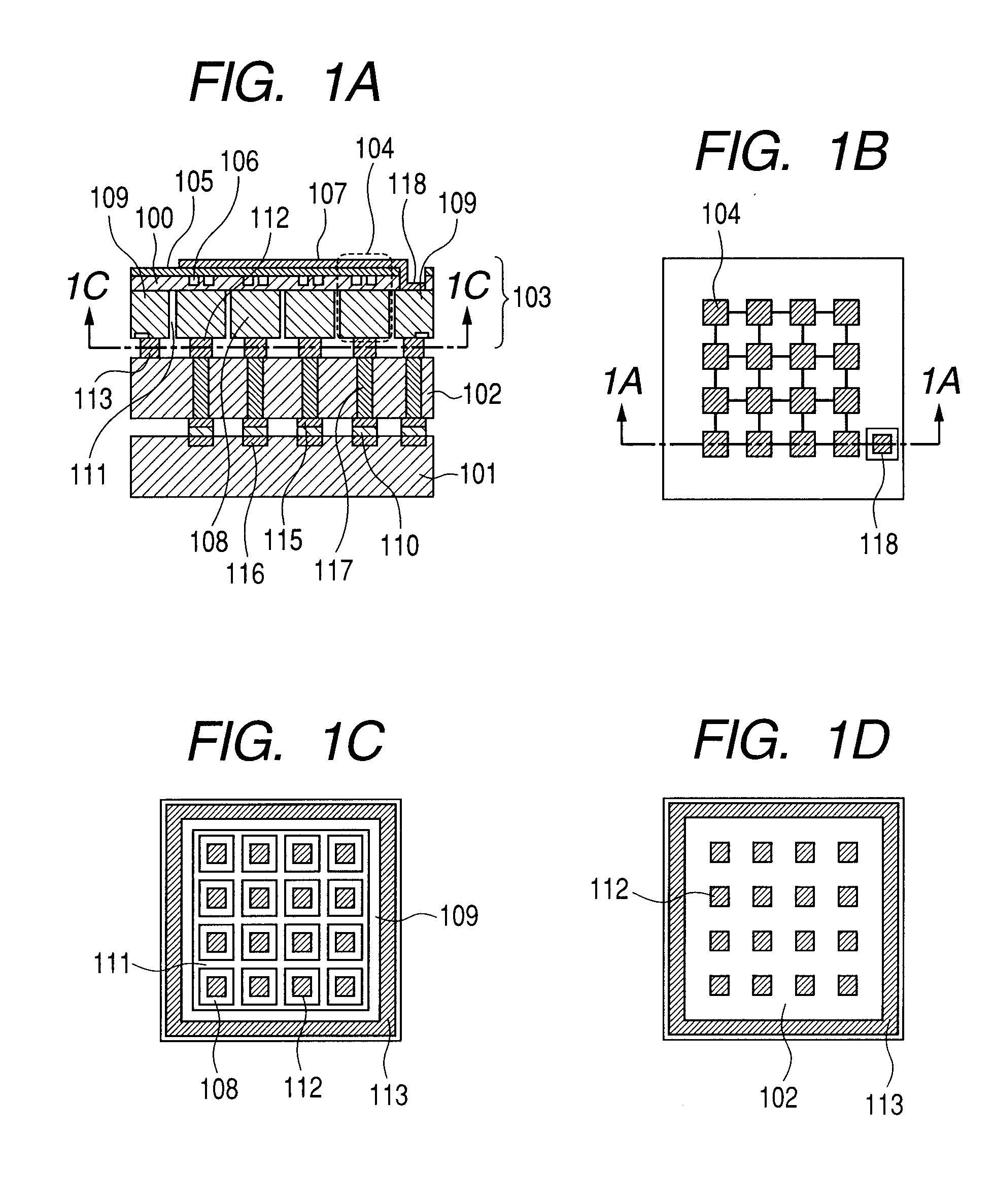
[0018]A CMUT according to a first embodiment of the present invention is described as an electromechanical transducer to which the present invention can be applied. FIGS. 1A to 1D illustrate this CMUT. However, the present invention is not limited to CMUTs and is applicable to any electromechanical transducer having a structure similar to that of CMUTs (structure in which a device substrate is partitioned by grooves to form first electrodes of the respective devices). For instance, the present invention is applicable to ultrasound transducers that use distortion, magnetic field, or light (so-called piezoelectric micromachined ultrasonic transducers (PMUTs), magnetic micromachined ultrasonic transducers (MMUTs), etc.). In other words, the present invention is not limited to electromechanical transducers in which the structure above lower electrodes 108 which are first electrodes described later is as described below.

[0019]FIG. 1A is a vertical sectional view taken along the line 1A-1...

second embodiment

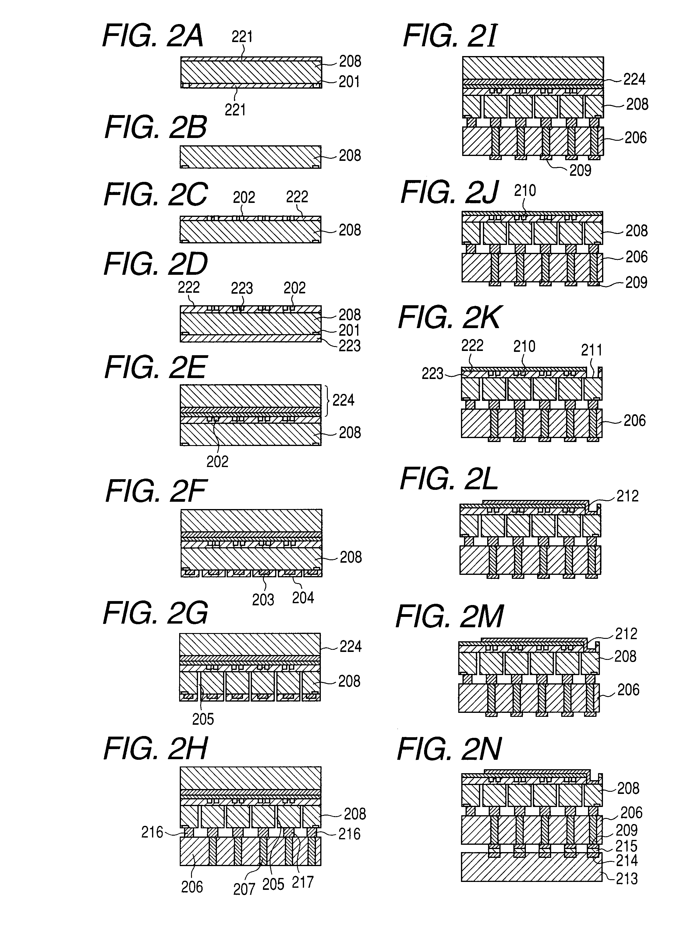
[0028]The second embodiment deals with a method of manufacturing a CMUT in which a device substrate and a wafer embedded with electrical through-wafer interconnects are bonded via an outer frame connection portion and lower electrode connection portions. FIGS. 2A to 2N which illustrate the process flow of this embodiment illustrate devices found in the vertical sectional view of FIG. 1A, but devices in the rest of the CMUT are also manufactured in the same manner.

[0029]A Si substrate 208 which serves as a device substrate is prepared first. The Si substrate 208 later constitutes lower electrodes and therefore is preferably low in resistivity. The Si substrate 208 used in this embodiment has a specific resistance of less than 0.02 Ω·cm. Oxide films 221 are formed on the Si substrate 208. Alignment marks 201 are formed by photolithography on the rear side of the substrate 208. The alignment marks 201 are formed by etching the rear side oxide film 221 with buffered hydrofluoric acid (B...


PUM

PropertyMeasurementUnit
Young's modulusaaaaaaaaaa
dielectric constantaaaaaaaaaa

Abstract

An electromechanical transducer, including: a plurality of devices each including at least one cell including a first electrode and a second electrode facing each other across a gap; and an outer frame extending along an outer periphery of the plurality of devices, wherein the first electrode of each of the devices each includes a plurality of portions formed by electrically separating a device substrate with grooves, wherein the outer frame includes a part of the device substrate surrounding the plurality of portions and electrically separated from the plurality of portions by the grooves, wherein the first electrodes each including the plurality of portions are respectively bonded to a plurality of conductive portions of another substrate via a plurality of electrode connection portions, and wherein the outer frame is bonded to a corresponding portion of the another substrate via a circular outer frame connection portion which surrounds the electrode connection portions.

Description

BACKGROUND OF THE INVENTION[0001]1. Field of the Invention[0002]The present invention relates to an electromechanical transducer such as an ultrasound transducer, and to a method of manufacturing the electromechanical transducer.[0003]2. Description of the Related Art[0004]A capacitive micromachined ultrasound (ultrasonic) transducer (CMUT) is a form of an electromechanical transducer. An example of CMUTs is constructed by electrically connecting a circuit board to a device substrate having multiple devices which include: a substrate having a lower electrode; a membrane, i.e., a vibration film supported by a supporter that is formed on the substrate having a lower electrode; and an upper electrode. Between the substrate having a lower electrode and the membrane, a cavity which is a gap is formed. The CMUT applies a voltage between the lower electrode and the upper electrode to cause the membrane to vibrate and thereby transmit ultrasound waves. The CMUT also receives ultrasound wave...

Claims


Application Information

Patent Timeline
Patent Type & Authority Applications(United States)
IPC IPC(8): H02N1/08H01R43/00
CPCY10T29/49117B06B1/0292
Inventor EZAKI, TAKAHIRO
Owner CANON KK
Why Eureka
Try Eureka