Micro-Electro-Mechanical Transducer Having a Surface Plate

a surface plate and micro-electromechanical technology, applied in the direction of mechanical vibration separation, waveguides, semiconductor electrostatic transducers, etc., can solve the problems of narrow bandwidth of pzt transducers, high cost, and difficult processing, so as to improve insulation performance and improve performance without increasing electrode gaps

Active Publication Date: 2010-01-21
KOLO MEDICAL (SUZHOU) CO LTD
View PDF35 Cites 55 Cited by
  • Summary
  • Abstract
  • Description
  • Claims
  • Application Information

AI Technical Summary

Benefits of technology

[0029]The base may comprise a through wafer interconnection, a layer having printed circuits, or an integrated circuit. The mass layer may have a holed or hallow structure or a honeycomb structure to improve performance.
[0030]In one embodiment, the spring anchor comprises an insulation extension extending into at least one of the base and the spring layer to improve the insulation performance without increasing the electrode gap.
[0031]Another aspect of the present invention is a micro-electro-mechanical transducer that has a base including a first electrode; a spring layer connected to the base; a

Problems solved by technology

This process is fraught with difficulties and high expenses, not to mention the large input impedance mismatch problem presented by such elements to transmit/receiving electronics.
In general, both matching layers and backing layers are needed for PZT transducer because the significant mismatch of the acoustic impedance between the PZT material and the medium.
One of the

Method used


Image

  • Micro-Electro-Mechanical Transducer Having a Surface Plate
  • Micro-Electro-Mechanical Transducer Having a Surface Plate
  • Micro-Electro-Mechanical Transducer Having a Surface Plate

Examples


first embodiment

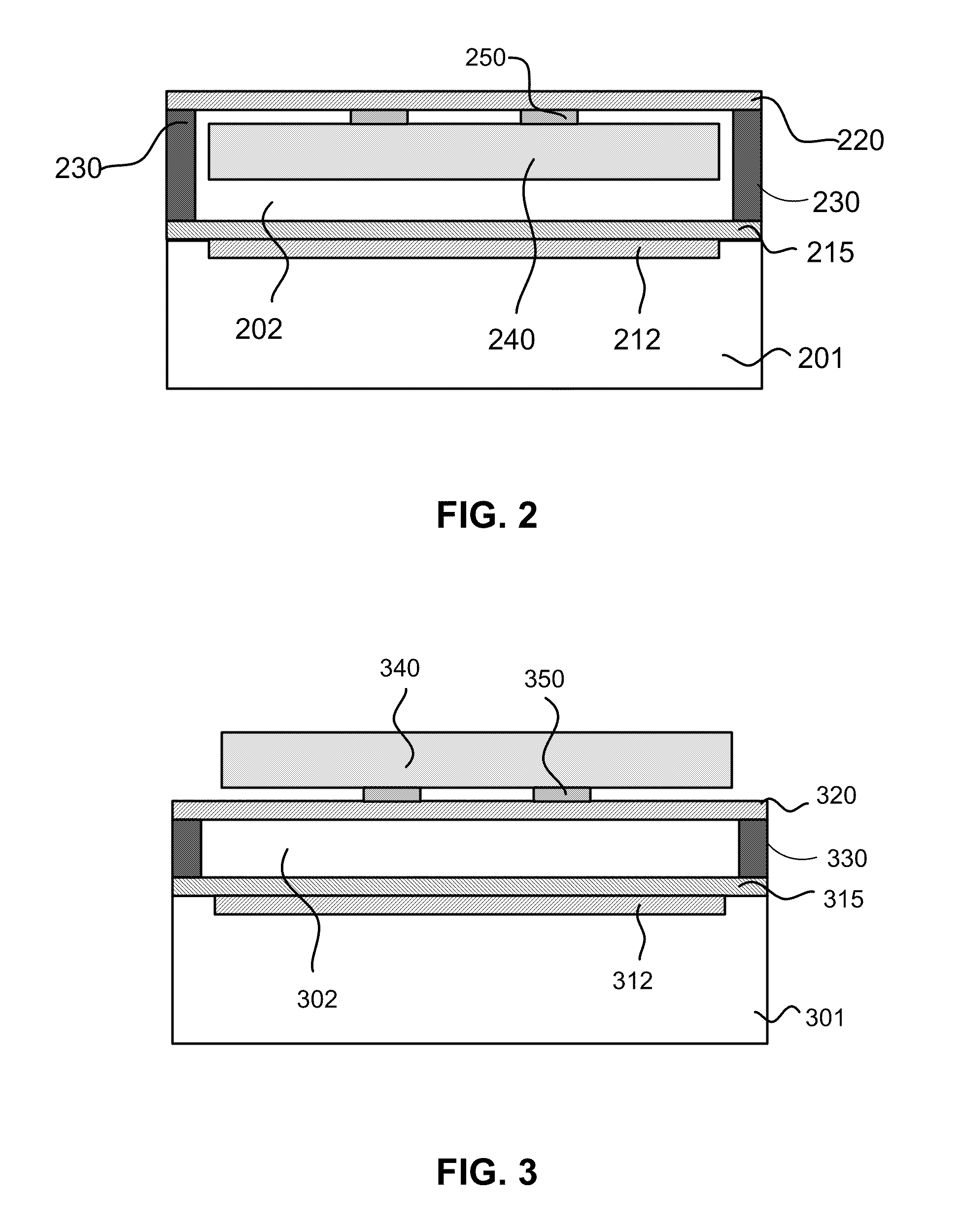
[0075]FIG. 2 shows a schematic cross-sectional view of a selected portion of the present invention in a cMUT having a flexible membrane surface. The cMUT in FIG. 2 has in a lower portion a base including substrate 201, bottom electrode 212, and insulation layer 215. The cMUT also has a spring layer 220 which may be a flexible membrane, and a mass layer 240 connected to the spring layer 220 through a spring-mass connector 250. The spring layer 220 is connected to insulation layer 215 through spring anchors 230. The insulation layer 215 is optional, and when used may also be placed on the bottom surface of the mass layer 240. The bottom electrode 212 may be a separate layer of conductive material (such as a metal), but may also be an integral part of the substrate 201 if the substrate 201 is conductive. Preferably, the mass layer 240 may include a top electrode (not separately shown). The top electrode may either be a separate layer of a conductive material or an integral part of the ...

second embodiment

[0079]FIG. 3 shows a schematic cross-sectional view of a selected portion of the present invention in a cMUT having a flexible membrane. The cMUT in FIG. 3 is similar to that shown in FIG. 2 except for the positioning of the mass layer in relation to be spring layer. As shown in FIG. 3, the cMUT has a lower portion including a base including substrate 301, bottom electrode 312, and insulation layer 315. The cMUT also has a spring layer 320 which may be a flexible membrane, and a mass layer 340 connected to the spring layer 320 through a spring-mass connector 350. Unlike that mean FIG. 2, the mass layer 340 are placed above the spring layer 320 and connected through the spring-mass connector 350 thereto.

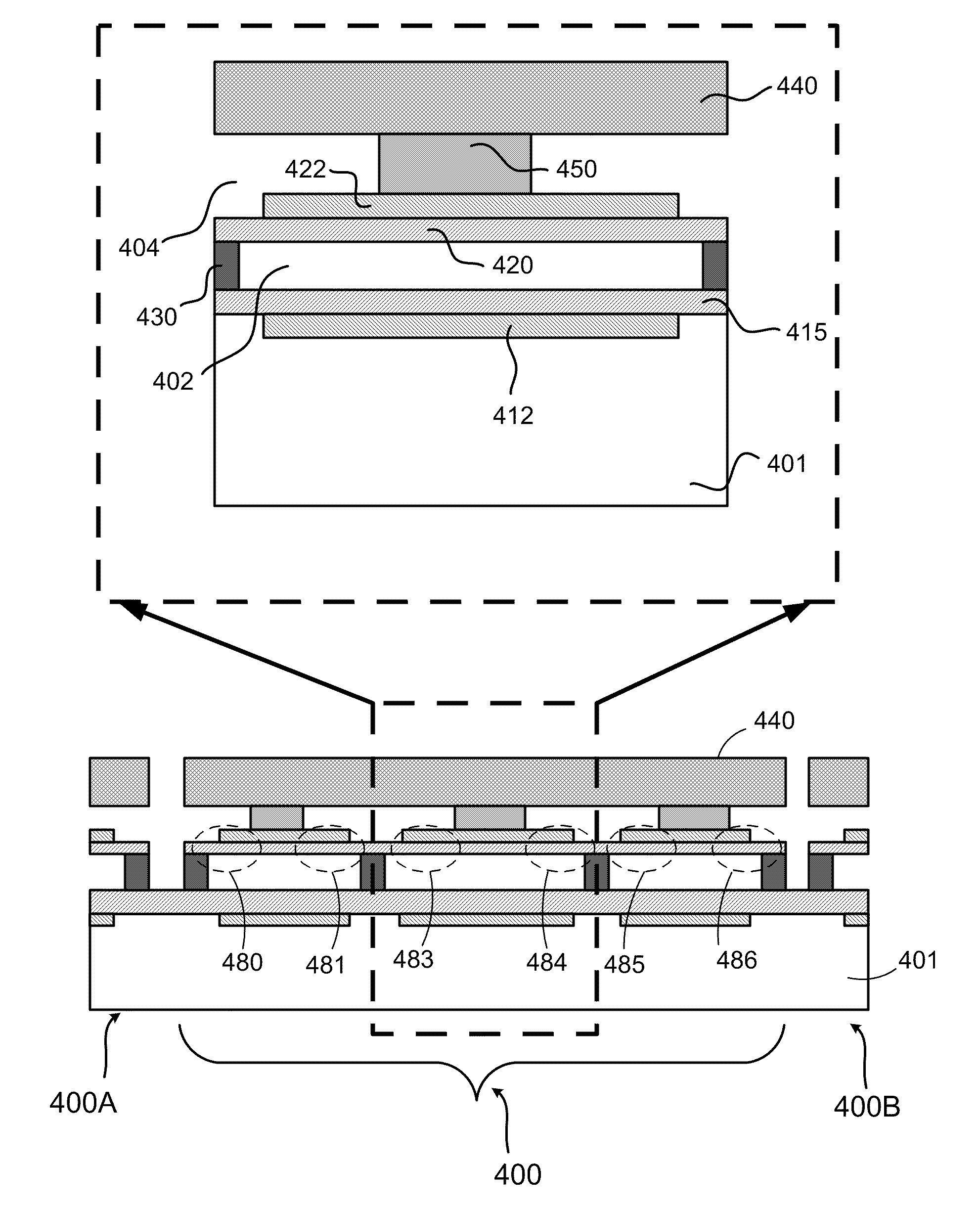
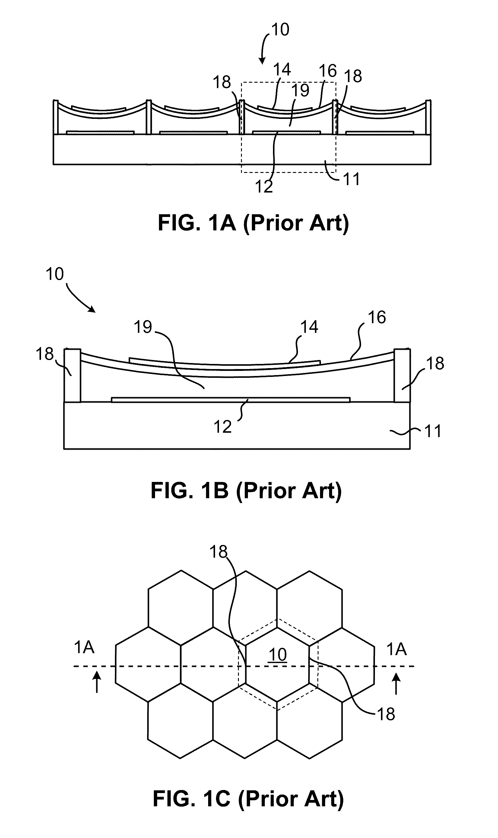
[0080]The cMUT structures shown in FIGS. 2-3 may be a basic unit (building block) of a complete cMUT. For example, when applied in conventional cMUTs with a flexible membrane surface, the structures shown in FIGS. 2-3 may be the structure for each cell, as shown in FIG. 1C, used to co...


PUM

PropertyMeasurementUnit
Lengthaaaaaaaaaa
Thicknessaaaaaaaaaa
Massaaaaaaaaaa

Abstract

A micro-electro-mechanical transducer (such as a cMUT) is disclosed. The transducer has a base, a spring layer placed over the base, and a mass layer connected to the spring layer through a spring-mass connector. The base includes a first electrode. The spring layer or the mass layer includes a second electrode. The base and the spring layer form a gap therebetween and are connected through a spring anchor. The mass layer provides a substantially independent spring mass contribution to the spring model without affecting the equivalent spring constant. The mass layer also functions as a surface plate interfacing with the medium to improve transducing performance. Fabrication methods to make the same are also disclosed.

Description

PRIORITY[0001]This application is a continuation of U.S. patent application Ser. No. 11 / 462,333, filed Aug. 30, 2006, which in turn claims benefit under 35 USC 119(e) from U.S. Provisional Application Ser. No. 60 / 705,606, filed Aug. 3, 2005, which applications are incorporated herein by reference in their entirety.[0002]This application further incorporates herein by reference in entirety the following:[0003]International Application (PCT) No. PCT / IB2006 / 051566, entitled THROUGH-WAFER INTERCONNECTION, filed on May 18, 2006;[0004]International Application (PCT) No. PCT / IB2006 / 051567, entitled METHODS FOR FABRICATING MICRO-ELECTRO-MECHANICAL DEVICES, filed on May 18, 2006;[0005]International Application (PCT) No. PCT / IB2006 / 051568, entitled MICRO-ELECTRO-MECHANICAL TRANSDUCERS, filed on May 18, 2006;[0006]International Application (PCT) No. PCT / IB2006 / 051569, entitled MICRO-ELECTRO-MECHANICAL TRANSDUCERS, filed on May 18, 2006;[0007]International Application (PCT) No. PCT / IB2006 / 05194...

Claims


Application Information

Patent Timeline
IPC IPC(8): H03H9/00H01L21/00
CPCH03H3/0072H03H9/02259H03H9/2405H03H9/462Y10T29/42H01L2924/0002Y10T29/49005H01L2924/00H04R2201/003B06B1/0292H04R19/005B81C1/00182B81C1/00357B81C1/00373B81C1/00523B81C1/00626H02N1/006B81B3/0027B81C1/00158
Inventor HUANG, YONGLI
Owner KOLO MEDICAL (SUZHOU) CO LTD
Why Eureka
Try Eureka