Method for manufacturing ceramic fired body and method for manufacturing honeycomb structured body

a technology of ceramic fired body and structured body, which is applied in the direction of ceramicware, furnaces, furnace heating elements, etc., can solve the problems of contamination of the environment and human body, and serious problems

Inactive Publication Date: 2011-05-26
IBIDEN CO LTD
View PDF6 Cites 11 Cited by
  • Summary
  • Abstract
  • Description
  • Claims
  • Application Information

AI Technical Summary

Problems solved by technology

In recent years, particulates such as soot in exhaust gases that are discharged from internal combustion engines for vehicles such as a bus and a truck, construction equipment and the like, have raised serious problems as contaminants harmful to the environment and the human body.

Method used


Image

  • Method for manufacturing ceramic fired body and method for manufacturing honeycomb structured body
  • Method for manufacturing ceramic fired body and method for manufacturing honeycomb structured body
  • Method for manufacturing ceramic fired body and method for manufacturing honeycomb structured body

Examples


first embodiment

[0063]Hereinafter, the first embodiment, which is one embodiment of the method for manufacturing a ceramic fired body of the present invention and the method for manufacturing a honeycomb structured body, will be described with reference to the drawings.

[0064]First, a continuous firing furnace used in the firing of the present embodiment will be described.

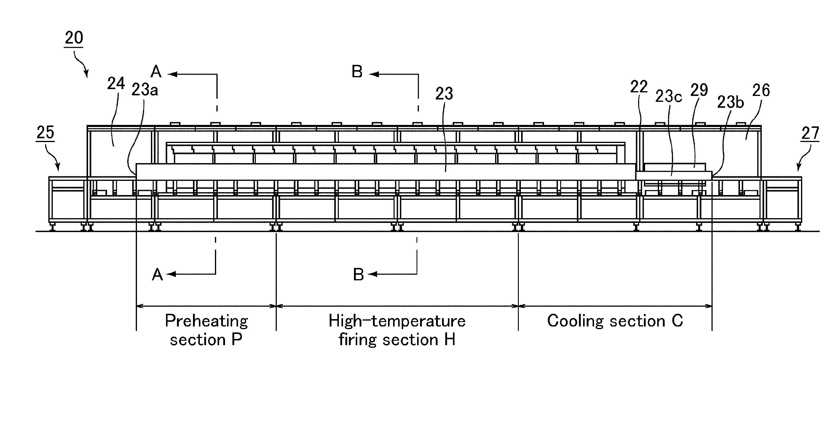
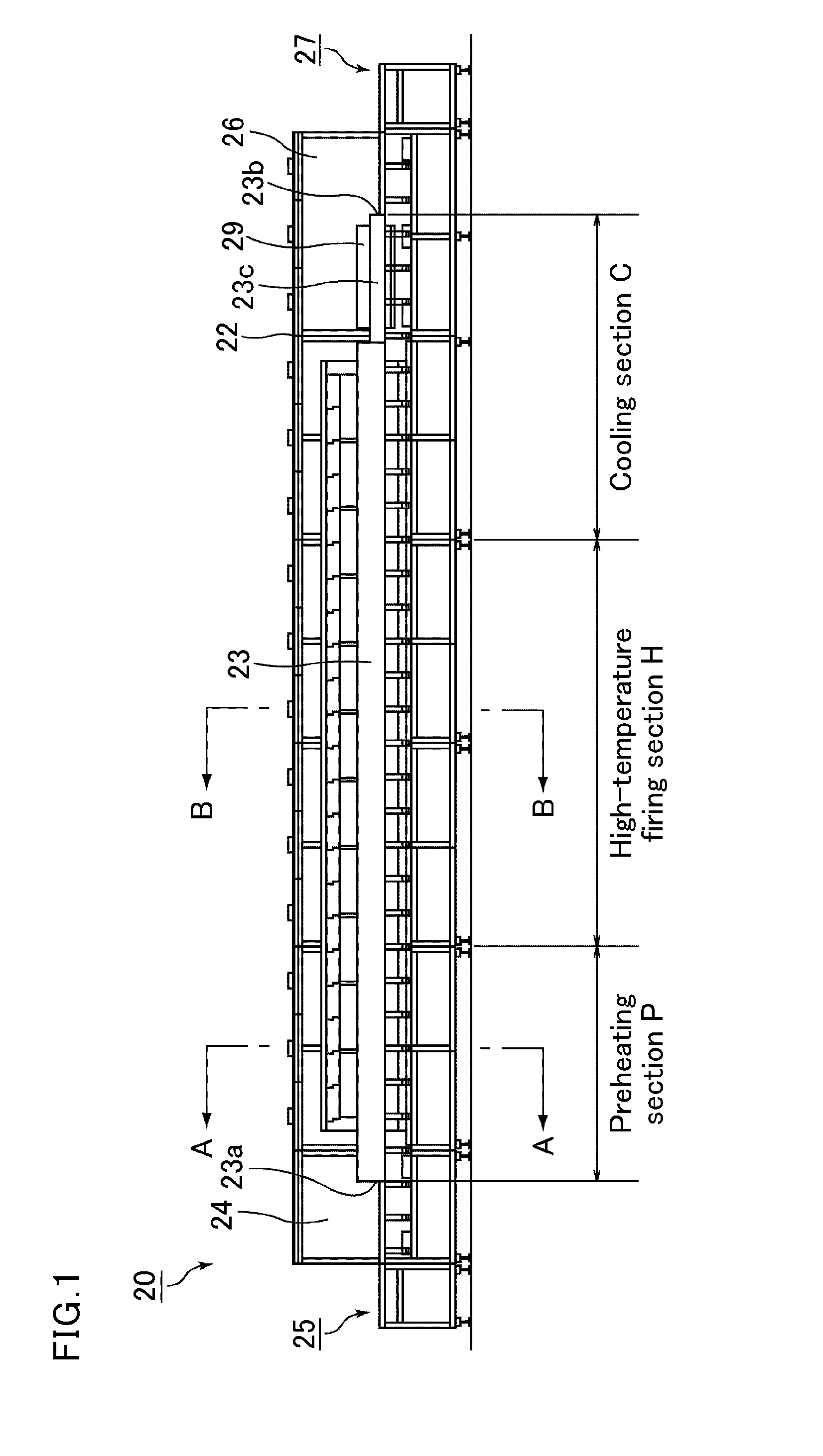
[0065]FIG. 1 is a front view schematically illustrating an example of a continuous firing furnace according to one embodiment of the present invention.

[0066]In the oblong body frame 22 of the continuous firing furnace 20 illustrated in FIG. 1, a tubular muffle 23 made of a heat-resistant material is transversely supported in most parts except an input part 25 and an exit part 27, and an inlet purge chamber 24 is formed in the vicinity of the inlet part 23a of the muffle 23. An input part 25 is provided forward of an inlet purge chamber 24, that is, on the left side in FIG. 1. A cooling jacket 29, a cooling means, is provided in a r...

example 1

Manufacturing of Honeycomb Degreased Body

[0168]An amount of 52.8% by weight of coarse powder of silicon carbide having an average particle diameter of 22 μm and 22.6% by weight of fine powder of silicon carbide having an average particle diameter of 0.5 μm were mixed. To the resulting mixture, 2.1% by weight of acrylic resin, 4.6% by weight of an organic binder (methylcellulose), 2.8% by weight of a lubricant (UNILUB, made by NOF Corporation), 1.3% by weight of glycerin, and 13.8% by weight of water were added, and then kneaded to prepare a mixture composition. The mixture composition was extrusion-molded and cut into a predetermined length, so that a raw honeycomb molded body having substantially the same shape as the shape illustrated in FIG. 6A and having cells not plugged was manufactured.

[0169]Next, the raw honeycomb molded body was dried with a microwave drying apparatus to give a dried body of the honeycomb molded body comprising a silicon carbide, with a size of 34.3 mm×34.3...

second embodiment

[0207]Hereinafter, the second embodiment, which is one embodiment of the present invention, will be described.

[0208]In the present embodiment, in the method for manufacturing a ceramic fired body and the method for manufacturing a honeycomb structured body according to the first embodiment, plural lines of the ceramic degreased bodies are arranged in the continuous firing furnace, plural lines of the upper and lower energizing electrodes are aligned with plural lines of the ceramic degreased bodies, and direct energizing heating was performed.

[0209]FIG. 7 is a perspective view schematically illustrating an example of a part in the high-temperature firing section of the continuous firing furnace used in the second embodiment of the present invention.

[0210]In FIG. 7, two ceramic degreased bodies 10 are disposed between one set of a lower plate 30 and an upper plate 31.

[0211]Two sets of lower electrodes 50 are disposed on the bottom of one set of the lower plate 30, and two sets of upp...


PUM

PropertyMeasurementUnit
temperatureaaaaaaaaaa

Abstract

A method for manufacturing a ceramic fired body includes molding and degreasing a ceramic raw material to manufacture a ceramic degreased body. The ceramic degreased body is fired in a continuous firing furnace. The firing step includes preheating the ceramic degreased body up to a preheating temperature of at least about 1500° C. and at most about 2000° C. by resistance heating with a resistance heating mechanism. High-temperature firing includes heating the ceramic degreased body from the preheating temperature to a firing temperature of at least about 2000° C. and at most about 2300° C. by both the resistance heating with the resistance heating mechanism and direct energizing heating in which the ceramic degreased body is energized and heated. The temperature of the ceramic degreased body is held at the firing temperature.

Description

CROSS-REFERENCE TO RELATED APPLICATIONS[0001]The present application claims priority under 35 U.S.C. §119 to PCT Application No. PCT / JP2009 / 069884, filed Nov. 25, 2009, the contents of which are incorporated herein by reference in their entirety.BACKGROUND OF THE INVENTION[0002]1. Field of the Invention[0003]The present invention relates to a method for manufacturing a ceramic fired body and a method for manufacturing a honeycomb structured body.[0004]2. Discussion of the Background[0005]In recent years, particulates such as soot in exhaust gases that are discharged from internal combustion engines for vehicles such as a bus and a truck, construction equipment and the like, have raised serious problems as contaminants harmful to the environment and the human body. For this reason, various applications in which honeycomb structured bodies made of porous ceramics are used as filters for capturing particulates in exhaust gases to purify the exhaust gases have been proposed.[0006]As suc...

Claims


Application Information

Patent Timeline
Patent Type & Authority Applications(United States)
IPC IPC(8): H05B3/62
CPCC04B35/64C04B38/0006C04B2111/00793C04B2235/6562C04B2235/666C04B2235/9623F27D11/02F27B9/063F27B9/36C04B35/00
Inventor SAIJO, TAKAMITSUHASHIMOTO, YOSHINORI
Owner IBIDEN CO LTD
Why Eureka
Try Eureka