

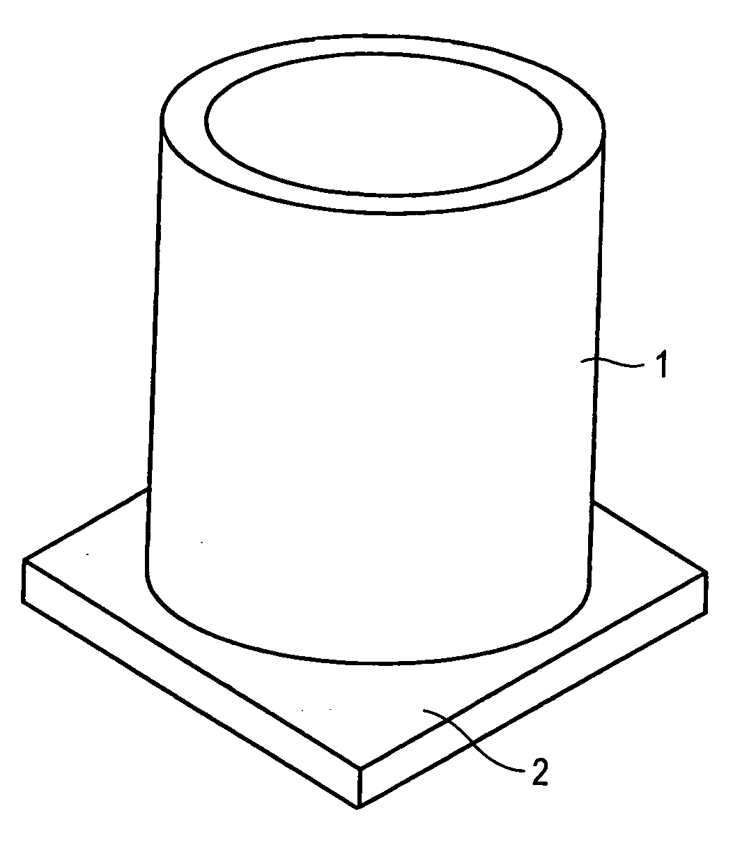
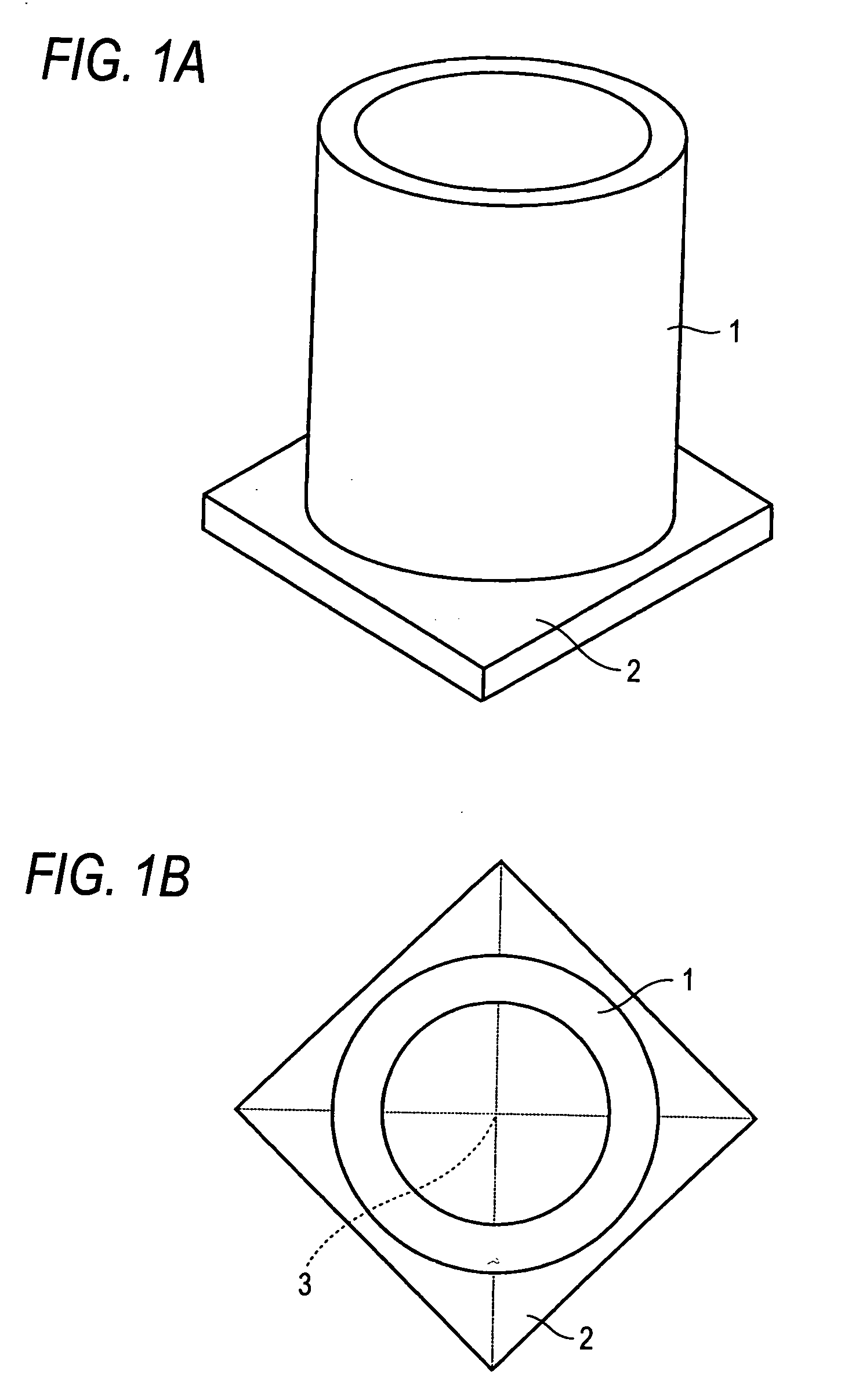
Cylindrical sputtering target, ceramic sintered body, and process for producing sintered body
a technology of which is applied in the direction of electrolysis components, vacuum evaporation coatings, coatings, etc., can solve the problems of large sintering shrinkage, sintering cracks, deformation or the like, and the inability to separate the cylindrical substrate and target material (sintering body) from the used target, and achieves high density
- Summary
- Abstract
- Description
- Claims
- Application Information
AI Technical Summary
Benefits of technology
Problems solved by technology
Method used
Image

Examples
example 1
[0050] Indium oxide having a 50% diameter (a particle diameter at 50% volume percent in the cumulative curve of the particle size distribution; hereinafter the same) of 0.54 μm and tin oxide having the diameter of 1.03 μm were mixed with a dry ball mill for 16 hours such that the compositional proportion is indium oxide: tin oxide=1:1 to prepare ITO mixed powder. The ITO mixed powder was taken out of a vessel, and 1.1% of a polycarboxylic acid type dispersing agent (solid content of the agent to the amount of the ITO mixed powder is 1.1%), 1.0% of a polyacrylic acid type binder (solid content of the binder to the amount of the ITO mixed powder is 1.0%), and 25.5% of ion-exchanged water (to the amount of the ITO mixed powder) were added to the powder. The resulting mixture was mixed with a ball mill for 16 hours to obtain a molding slurry. Viscosity of this slurry was measured, and it was found to be 680 centipoise.
[0051] A polyalkylene glycol type defoaming agent was added to the s...
example 2
[0065] Indium oxide powder and tin oxide powder each were pulverized with a dry ball mill for 48 hours. The tin oxide powder was further subjected to dry jet mill pulverization. 50% diameters of indium oxide powder and tin oxide powder at this stage were 0.46 μm and 0.28 μm, respectively. Those powders were dry mixed in the same manner as in Example 1, and a slurry was prepared using the resulting mixture in the same manner as in Example 1. As a result of measurement of viscosity of this slurry, it was found to be 870 centipoise.
[0066] Centrifugal molding was conducted and the resulting molding was dried, in the same manner as in Example 1. CIP treatment was applied to the molding under pressure of 3 ton / cm2. Dewaxing and sintering were conducted in the same manner as in Example 1 except for changing the sintering conditions as follows, thereby preparing ten sintered bodies.
Sintering Conditions
[0067] Charge weight / oxygen flow rate: 0.38 kg·min / liter
[0068] Temperature rising rat...
example 3
[0074] ITO mixed powder was prepared in the same manner as in Example 1. Paraffin as a binder was added to the powder in an amount of 1.5% (based on the amount of ITO mixed powder).
[0075] A cylindrical urethane rubber mold having an inner diameter of 140 mm (wall thickness: 7 mm) and a length of 220 mm, having closing lids at the upper and the lower thereof, and containing a columnar core (shaft) was filled with the powder obtained above while tapping. The rubber mold was closed, and CIP treatment was conducted under a pressure of 3 ton / cm2 to obtain a molding. This molding was processed with a lathe to an outer diameter of 121 mm, an inner diameter of 93 mm and a length of 200 mm. Dewaxing and sintering were conducted in the same manner as in Example 1 except for changing the sintering conditions as follows, thereby preparing ten sintered bodies.
Sintering Conditions
[0076] Charge weight / oxygen flow rate: 1.00 kg min / liter
[0077] Temperature rising rate: 50° C. / hr
[0078] Sinterin...
PUM
| Property | Measurement | Unit |
|---|---|---|
| shrinkage | aaaaa | aaaaa |
| density | aaaaa | aaaaa |
| density | aaaaa | aaaaa |
Abstract
Description
Claims
Application Information