Light transmissible resonators for circuit and antenna applications

a technology of transmissible resonators and antennas, applied in the direction of electrically short antennas, antennas, electrical equipment, etc., can solve the problems of increasing the antenna gain from about 5 dbi to 0 dbi, increasing the cost of reducing the transparency of the antenna, and challenging the problem of high conducting transparent films

Active Publication Date: 2011-05-26
CITY UNIVERSITY OF HONG KONG
View PDF4 Cites 72 Cited by
  • Summary
  • Abstract
  • Description
  • Claims
  • Application Information

AI Technical Summary

Benefits of technology

[0015]The present invention provides a circuit for an electronic device having a transparent resonator. The transparent resonator may be mounted on the circuit so as to at least partially occupy a footprint of another component of the circuit. The transparent resonator may be mounted on said circuit such that it comprises a part of a light pathway for said another component so as to allow light impinging on said resonator component to reach said another component or to allow light generated by said another component to be transmitted away from said another component. In one particular embodiment a dual function transparent, shaped (preferably hemispherical) DRA that simultaneously functions as an antenna and a focusing lens for a solar cell is provided. To make the system compact, the solar cell is placed beneath the DRA to save the footprint on the ground plane or grounded substrate of the DRA. The DRA can also serve as a protective cover for the solar cell. A conformal strip or feedline strip is used to excite the transparent, shaped DRA in its dominant TE111 mode. Due to its focusing effect, the shaped DRA can increase the output voltage and current of the solar cell. The solar cell can be employed to power an electronic device such as a wireless communication device, e.g. a personal digital assistant (PDA), a mobile phone, although many other wireless enabled devices can also be envisaged such as a remote controller or the like. The solar cell with integrated or combined DRA can also be employed in other more substantial communication devices such as wireless communication base stations.
[0020]The transparent DRA is proposed to circumvent the problem associated with known transparent microstrip antennas in that the transparent DRA of the invention does not need any conducting parts to resonate. More importantly, it can provide an antenna gain of more than 4 dBi across its entire passband, which is a new achievement for a transparent antenna.

Problems solved by technology

The transparent microstrip antenna has been studied for optical applications, but having a highly conducting transparent film is still a challenging problem.
Using this technique, the antenna gain has been increased from about −5 dBi to ˜0 dBi, but at the cost of reducing the transparency of the antenna.
In order to solve this problem, it has been proposed to use a slot antenna, but this requires a removal of part of the solar cell panel which is undesirable.

Method used


Image

  • Light transmissible resonators for circuit and antenna applications
  • Light transmissible resonators for circuit and antenna applications
  • Light transmissible resonators for circuit and antenna applications

Examples


first embodiment

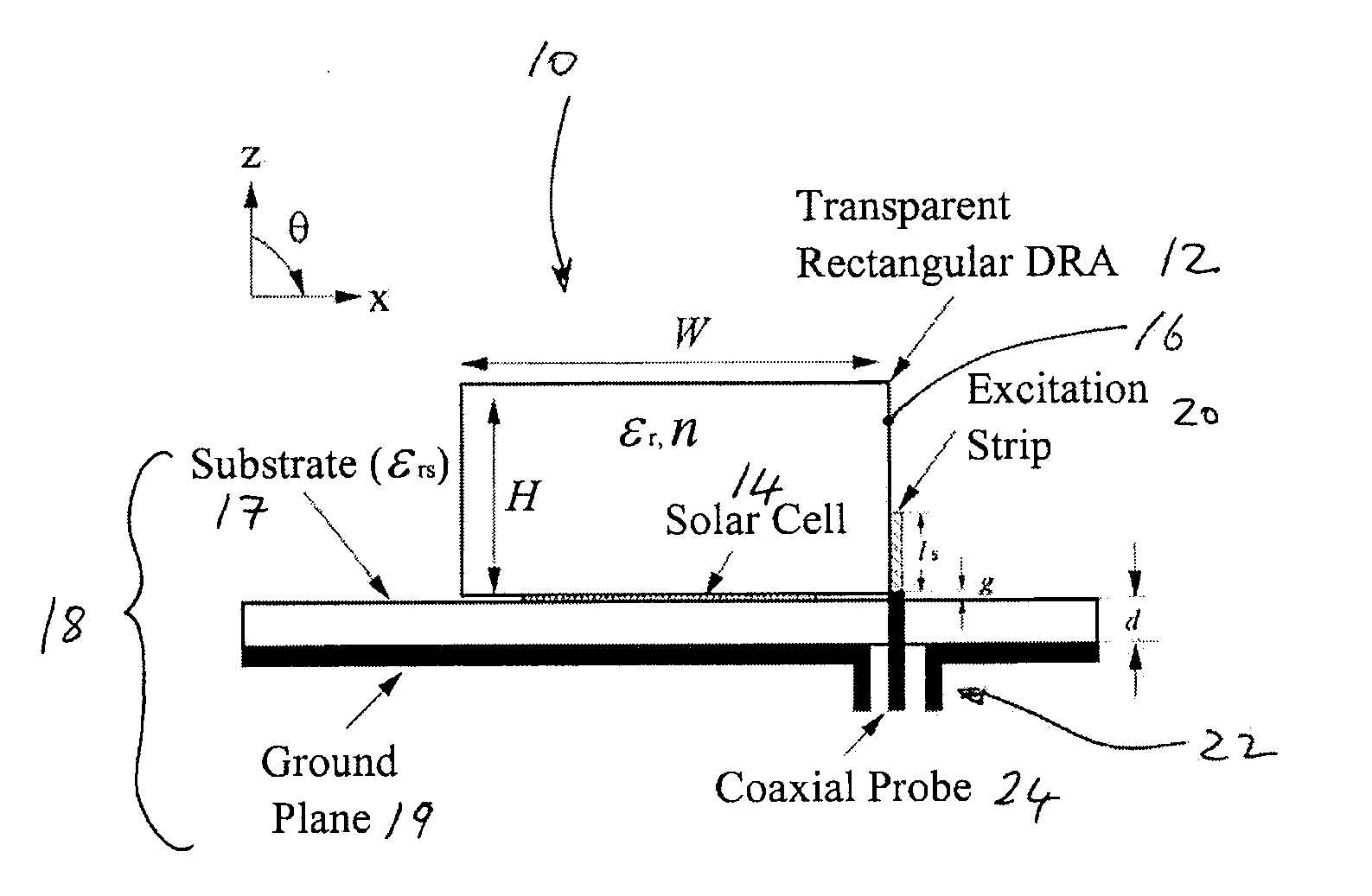
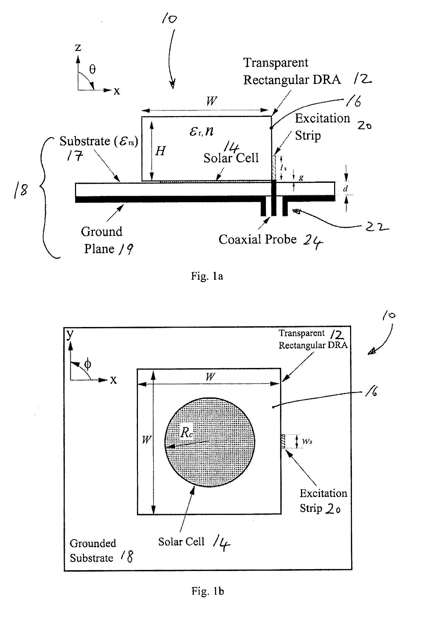
[0051]Referring to FIGS. 1a and 1b, a circuit 10 including a DRA 12 in accordance with the invention is described. This embodiment of a DRA 12 comprises a non-focusing transparent rectangular DRA 12. As a rectangular DRA is mechanically easier to fabricate than other shapes, it is of great interest to antenna engineers.

[0052]In this case, the DRA 12, in addition to serving as an antenna, serves as a protective cover for an underlaid solar cell 14. As the DRA 12 is transparent, it does not deter the solar cell 14 from collecting sunlight or ambient light. In addition, high compactness can be easily achieved by placing the solar cell panel 14 beneath the DRA 12 in order to reduce or minimize the footprint occupied by the combined components. The DRA 12 comprises a dielectric resonator (DR) element 16; a ground plane or grounded substrate 18 comprising a non-conductive substrate 17 and a conductive ground plane layer 19; and a strip feedline (conformal strip) 20 for exciting the DR ele...

second embodiment

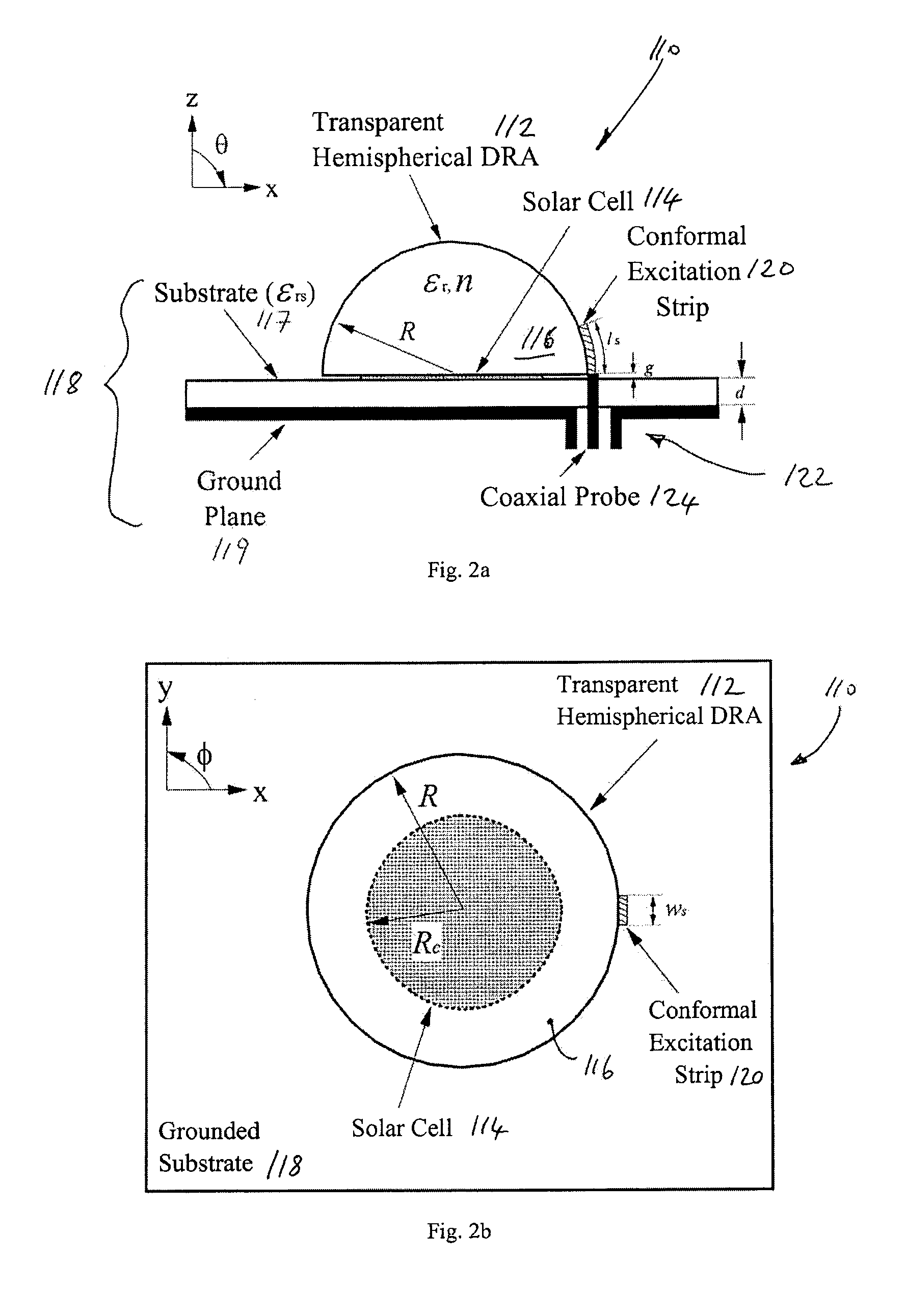
[0056]Referring to FIGS. 2a and 2b, a DRA 112 in accordance with the invention is described. This embodiment of a DRA 112 is mounted on a circuit 110 of an electronic device or system (not shown) and comprises a focusing transparent DRA 112 which is shaped to focus light impinging on its upper surface and to convey the focused light to a selected region on a lower surface thereof adjacent an underlaid solar cell. The selected region may be chosen as a region that maps to or overlaps a light receiving part of the solar cell 114 when the DRA 112 is mounted on the circuit 110 above the solar cell 114.

[0057]In this case, the DRA 112, in addition to serving as an antenna and a protective cover for the underlaid solar cell 114, also acts to focus captured light onto a light receiving part of the solar cell 114 thereby enhancing performance of the solar cell whilst preserving a compact form by sharing a footprint with the solar cell 114. In this embodiment, the DRA 112 also comprises a die...


PUM


Abstract

Provided is a circuit for an electronic device having a non-planar transparent resonator. The transparent resonator is mounted on said circuit so as to at least partially occupy a footprint of another component of the circuit. The transparent resonator forms part of a light pathway on said circuit for transmitting light to or from said another component. Also provided is a transparent dielectric resonator antenna (DRA) for optical applications. Since the DRA is transparent, it can let light pass through itself and, thus, the light can be utilized by an optical part of a system or device. The transparent DRA can be placed on top of a solar cell. Since the DRA does not block the light, the light can reach the solar cell panel and power can be generated for the system or device. The system or device so obtained is very compact because no extra footprint is needed within the system or device for the DRA. It finds application in compact wireless applications that need a self-sustaining power device.

Description

FIELD OF THE INVENTION[0001]The invention relates to a light transmissible resonator for circuit and antenna applications and more particularly to a dielectric resonator antenna having a light transmissable dielectric resonator element preferably shaped to focus light impinging on a surface of said resonator element.BACKGROUND OF THE INVENTION[0002]Resonators have been widely used in microwave and millimeter wave circuits such as filters, oscillators and antennas, for example. These components comprise important parts of many wireless systems and devices, although their uses are not confined to wireless applications.[0003]It is also known that a dielectric resonator (DR) can be used as a circuit element in oscillator and filter circuits, or as an effective radiator that is now commonly known as a DR antenna (DRA). In the past two decades, the DRA has been studied extensively due to a number of advantages it provides such as its small size, low loss, low cost, light weight, and ease ...

Claims


Application Information

Patent Timeline
Patent Type & Authority Applications(United States)
IPC IPC(8): H01Q13/00
CPCH01Q9/0485
Inventor LEUNG, KWOK WALIM, ENG HOCK
Owner CITY UNIVERSITY OF HONG KONG
Why Eureka
Try Eureka