
Optical transmitters for mm-wave rof systems

a technology of optical transmitter and rof system, which is applied in the direction of electromagnetic transmission, semiconductor amplifier structure, semiconductor laser, etc., can solve the problems of low modulation depth, poor link efficiency, signal-to-noise ratio, etc., and achieves high optical link efficiency, high bit rate, and high spectral efficiency

Inactive Publication Date: 2011-05-26
CORNING OPTICAL COMM LLC
View PDF6 Cites 137 Cited by
  • Summary
  • Abstract
  • Description
  • Claims
  • Application Information

AI Technical Summary

Benefits of technology

[0014]The devices and methods disclosed herein enable higher optical link efficiency, higher spectral efficiency, higher bit rate, extended RoF links and longer wireless transmission distances in optical transmission systems. Additionally, the disclosed devices and methods provide relatively low cost ways to achieve the aforementioned attributes.

Problems solved by technology

One important drawback of known OIL VCSEL devices is that the attainable modulation depth (i.e., the ratio between the modulated signal power and the optical carrier power) is very small.
This drawback arises from the fact that the optical output of the OIL VCSEL is spatially and spectrally coincident with the master laser's optical power, which is reflected by the VCSEL itself.
In general, weakly modulated optical signals lead to poor link efficiency because the imbalance between the optical carrier and the modulated sideband leads to a poor signal-to-noise ratio (SNR) of the detected electrical / RF signal, thus causing a high BER (bit error rate).
However, in OIL devices, this limitation cannot be overcome by reducing the power of the master laser or increasing the output power of the VCSEL, because doing so would modify the injection ratio away from the value necessary to obtain the desired frequency response.

Method used


Image

  • Optical transmitters for mm-wave rof systems
  • Optical transmitters for mm-wave rof systems
  • Optical transmitters for mm-wave rof systems

Examples


example 1

Conventional Transmitter without Equalization of VCSEL Output

[0074]An experimental setup of a conventional OIL VCSEL RoF transmission system was constructed as shown in FIG. 8. In this setup, a Head-End Unit or HEU 500 was coupled to a remote antenna unit or RAU 510 by optical fiber 520. The HEU 500 consisted of a pulse pattern generator PPG, a low pass filter LPF, a bias T B-T, a slave VCSEL, a high-power Master Laser, and a custom-made one-step 60 GHz electrical up-converter. The remote antenna unit 510 included an optical-to electrical converter O / E, a low noise amplifier LNA, and a bandpass filter BPF. The signal from the remote antenna unit 510 was down-converted to baseband by a one-step 60 GHz down-converter, and fed into a bit error rate tester (BERT) 560. The VCSEL was a 1540 nm single-mode buried tunnel junction (BTJ) VCSEL with a maximum output power of ˜3 mW, and ˜70% coupling efficiency to a lensed fiber. The ML was a high-power Distributed Feedback (DFB) laser, which w...

example 2

Transmitter with Bandpass Filtering / Equalization of VCSEL Output

[0085]Experimental Setup

[0086]To improve the sensitivity of the RoF system of Example 1 above, it was necessary to reduce the large CSR observed above. Thus, the experimental setup of FIG. 14 was constructed. The setup is generally arranged as a Head-End Unit 600 connected to a remote antenna unit 610 by optical fiber 620, which communicates with a 60 GHz wireless receiver 650. The arrangement included a pulse pattern generator PPG, arbitrary waveform generator AWG, low pass filter LPF, bias T B-T, band pass filter BPF, optical bandpass filters OBPF 1, OBPF 2 and OBPF 3, erbium doped fiber amplifiers EDFA, bit error rate tester (BERT) 660, and vector signal analyzer (VSA) 670. In this setup, a tunable filter was used to reduce the master carrier power. Given that the large CSR observed above was similar in value to the contrast ratio of typical tunable optical filters, placing the passband of a single optical bandpass f...


PUM


Abstract

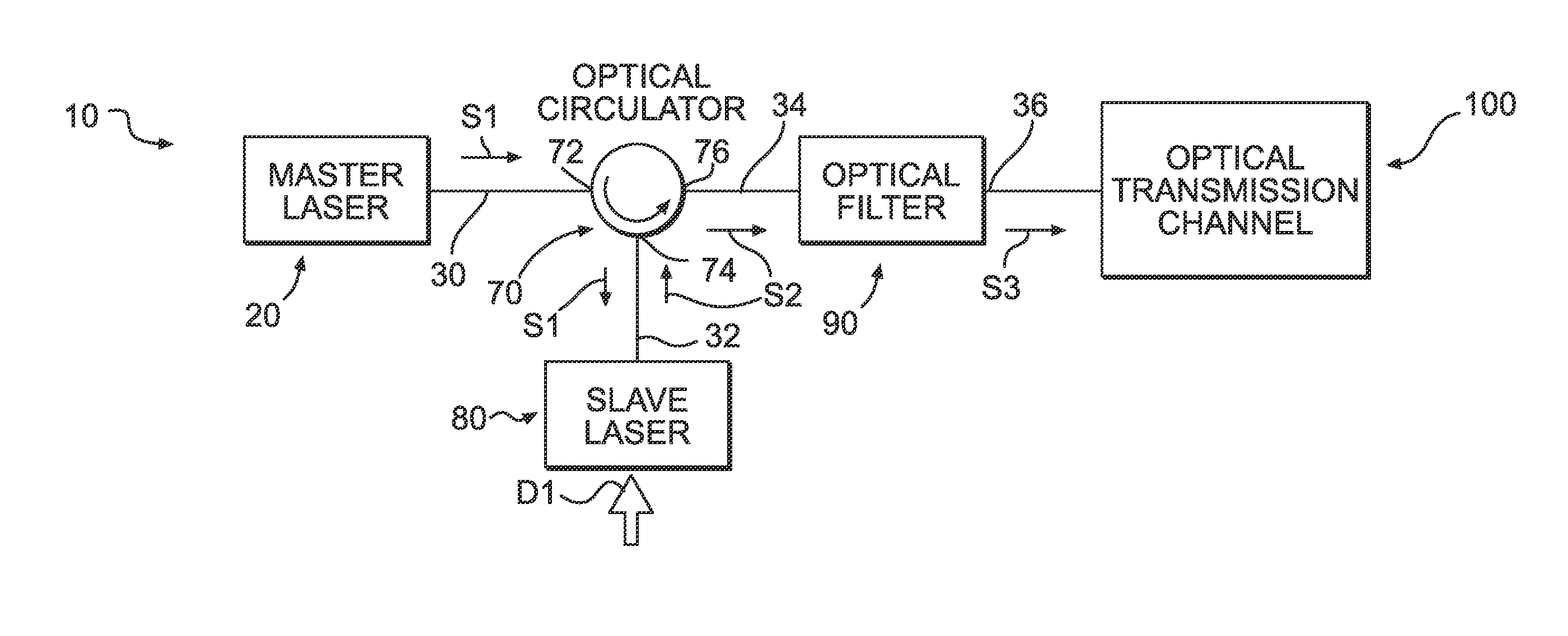
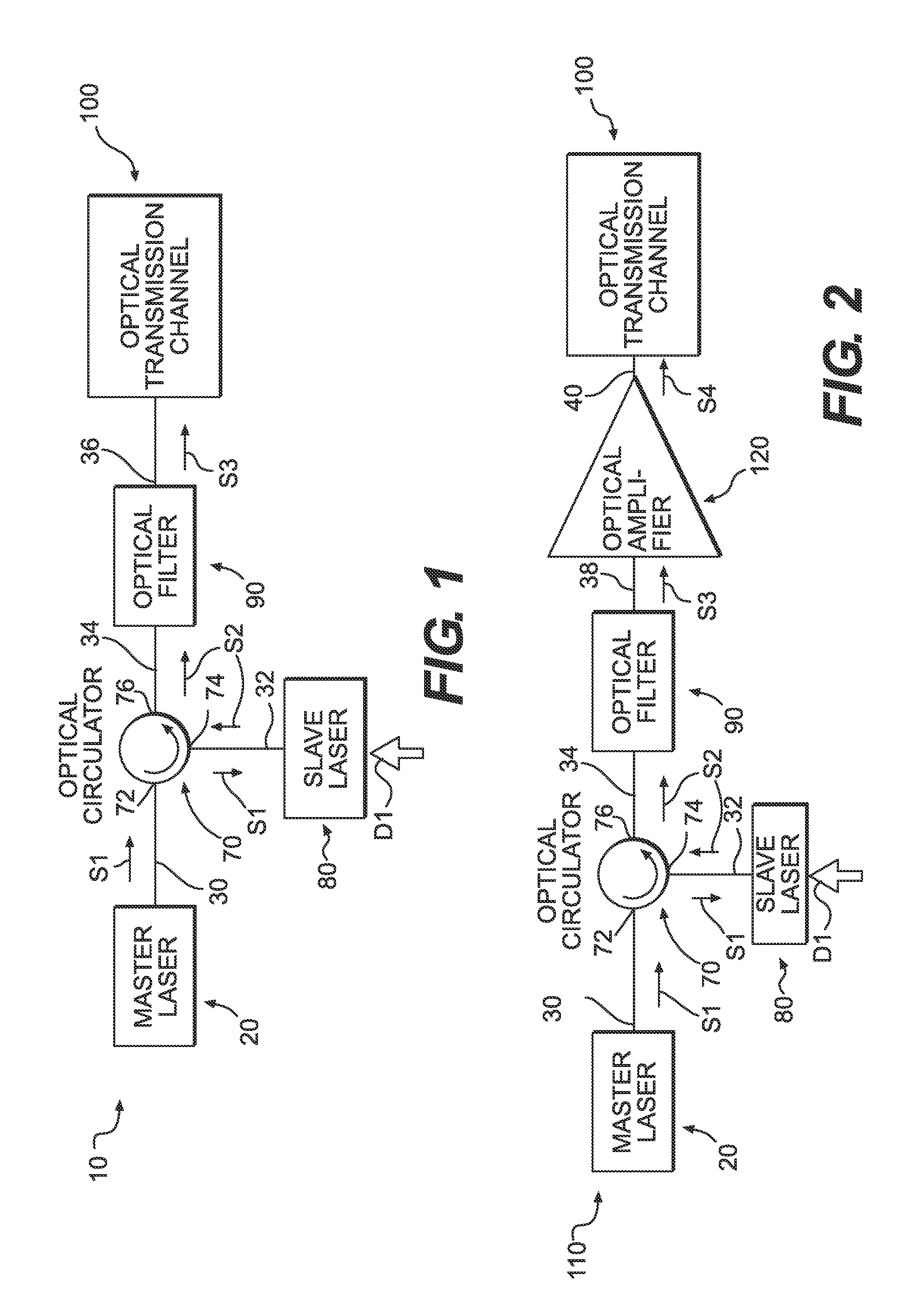
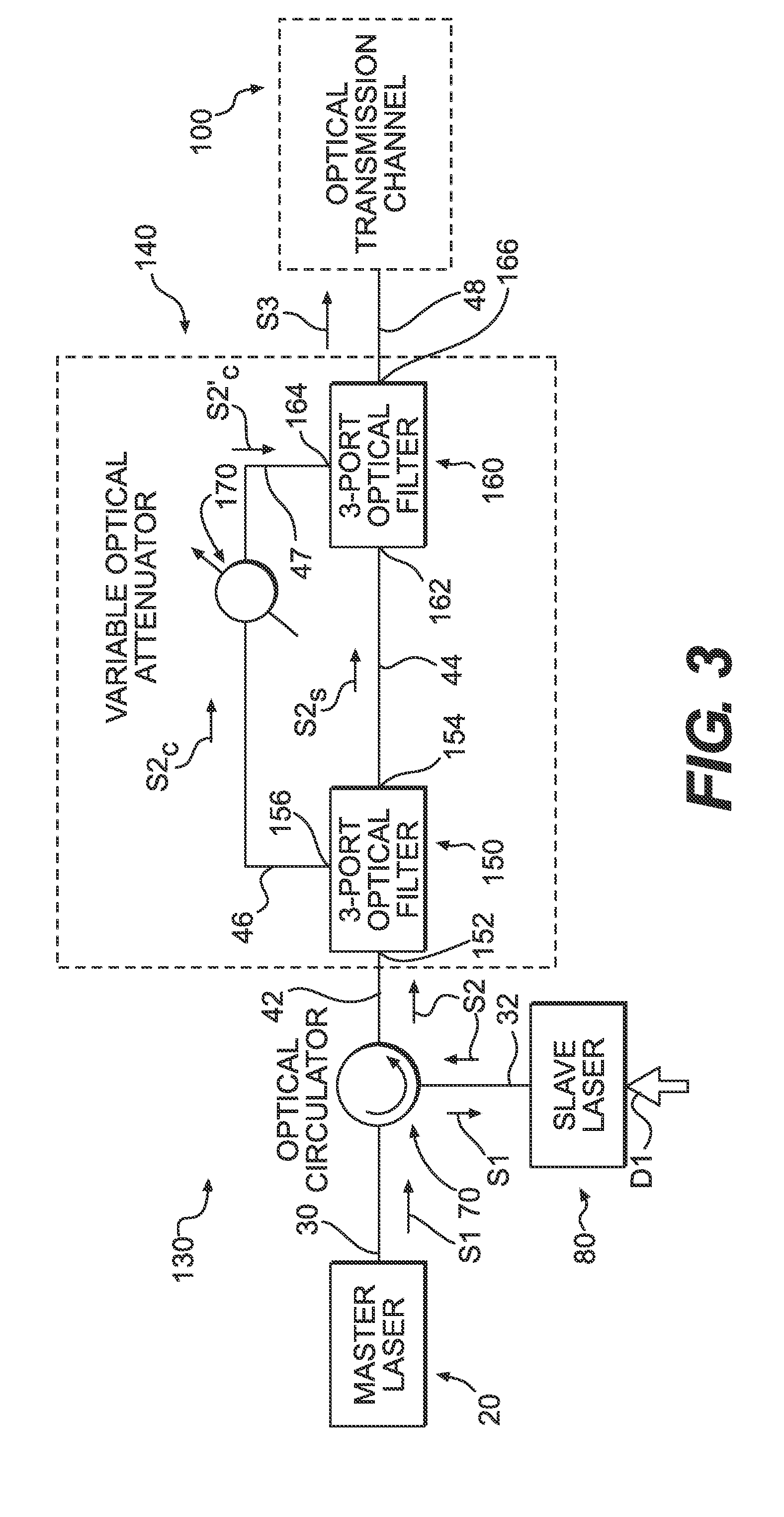
Optical transmitters for radio over fiber systems are disclosed. More particularly, the optical transmitters include optically-injection-locked vertical cavity surface-emitting laser devices (OIL VCSELS). The transmitters include a master laser, at least one slave laser injection-locked by the master laser, and an equalizer / filter unit that enables the ratio of the carrier power to the sideband power in the output signal of the transmitter to be varied and optimized independently of the injection ratio of the transmitter.

Description

PRIORITY APPLICATION[0001]This application claims the benefit of U.S. Provisional Application No. 61 / 263,124, filed Nov. 20, 2009, the entire contents of which are incorporated by reference.BACKGROUND[0002]1. Technical Field[0003]The disclosure relates to optical transmission devices, and more particularly to optically injection-locked semiconductor laser devices for high speed optical transmission.[0004]2. Technical Background[0005]Optically injection-locked (OIL) semiconductor lasers are promising optical sources for high-speed optical transmission because they exhibit enhanced frequency response, and are therefore suitable for direct modulation. The enhanced frequency response is of particular importance for multi-Gbps fiber-wireless systems operating at millimeter wave frequencies, such as 60 GHz. In optical injection-locking, the optical output from a master laser is injected into a slave laser. Under particular conditions, the slave laser is “locked” to the master, i.e., the l...

Claims


Application Information

Patent Timeline
IPC IPC(8): H01S5/183H01S5/50
CPCH01S5/0078H01S5/183H04B10/25759H01S5/50H01S5/4006
Inventor BENJAMIN, SELDON D.FORTUSINI, DAVIDE D.NG'OMA, ANTHONYSAUER, MICHAEL
Owner CORNING OPTICAL COMM LLC
Learn More