Fuel cell

a fuel cell and fuel cell technology, applied in the field of fuel cells, can solve the problems of reducing the frequency of electrochemical reactions, affecting the efficiency of pefc, so as to reduce the flow rate of reaction gas passing, inhibit the desiccation of mea, and increase the side surface area

Active Publication Date: 2011-05-26
TOYOTA JIDOSHA KK
View PDF1 Cites 6 Cited by
  • Summary
  • Abstract
  • Description
  • Claims
  • Application Information

AI Technical Summary

Benefits of technology

[0016]In the fuel cell of the present invention, the depth of the upstream region of the inlet passage is larger than that of the downstream region of the inlet passage. This structure enables to lower the flow rate of the reaction gas passing at the upstream region of the inlet passage and enables to inhibit desiccation of the MEA by inhibiting removal of excessive amount of water from the MEA. In addition, by enlarging not the width but the depth of the inlet passage at the upstream region, it becomes possible to increase the side surface area of inlet passage cooled with a cooling medium passing through inside the separator; thereby it is capable of easily inhibiting desiccation. Moreover, by making the depth of the downstream region of the inlet passage be smaller than that of the upstream region of the inlet passage, it becomes possible to raise flow rate of the reaction gas passing at the downstream region of the inlet passage. So, this can inhibit flooding at the downstream region of the inlet passage and at the laminated body facing the downstream region of the inlet passage. Hence, according to the fuel cell of the invention, the invention can provide a fuel cell having a blocked passage and showing capability of inhibiting desiccation and flooding of the MEA.
[0017]Further, in the fuel cell of the invention, by making the depth of the downstream region of the outlet passage be larger than that of the upstream region of the outlet passage, it becomes possible to lower the flow rate of the reaction gas passing at the downstream region of the outlet passage; thereby it is possible to inhibit desiccation of the MEA by inhibiting removal of excessive amount of water from the MEA facing the downstream region of the outlet passage. In addition, by enlarging not the width but the depth of the outlet passage at the downstream region, it becomes possible to increase the side surface area of outlet passage cooled with a cooling medium passing through inside the separator; thereby it is capable of easily inhibiting desiccation. Moreover, by making the depth of the upstream region of the outlet passage be smaller than that of the downstream region of the outlet passage, it becomes possible to raise flow rate of the reaction gas passing at the upstream region of the outlet passage. Therefore, this can inhibit flooding at the upstream region of the outlet passage and at the laminated body facing the upstream region of the outlet passage. Hence, according to the mode, the invention can easily inhibit desiccation and flooding of the MEA.
[0018]Still further, in the fuel cell of the invention, since separators having the inlet passages or both the inlet passages and the outlet passages those of which depth is controlled are arranged on at least the cathode catalyst layer side, distribution of water can be homogenized at the cathode catalyst layer side where desiccation and flooding of the MEA tend to occur. Accordingly, by the above mode, desiccation and flooding of the MEA can be easily inhibited.

Problems solved by technology

Therefore, within the MEA, mal-distribution of water may be caused.
At the downstream of the reaction-gas flow direction, liquid water tends to be pooled and the pooled water often causes flooding.
When the MEA is dried, proton conductivity resistance increases which results in decrease in PEFC's electricity generating performance.
In addition, once flooding is caused, diffusion of reaction gas is inhibited, which results in decrease in frequency of occurrence of electrochemical reaction; thereby PEFC's electricity generating performance is decreased.

Method used


Image

  • Fuel cell
  • Fuel cell
  • Fuel cell

Examples


Embodiment Construction

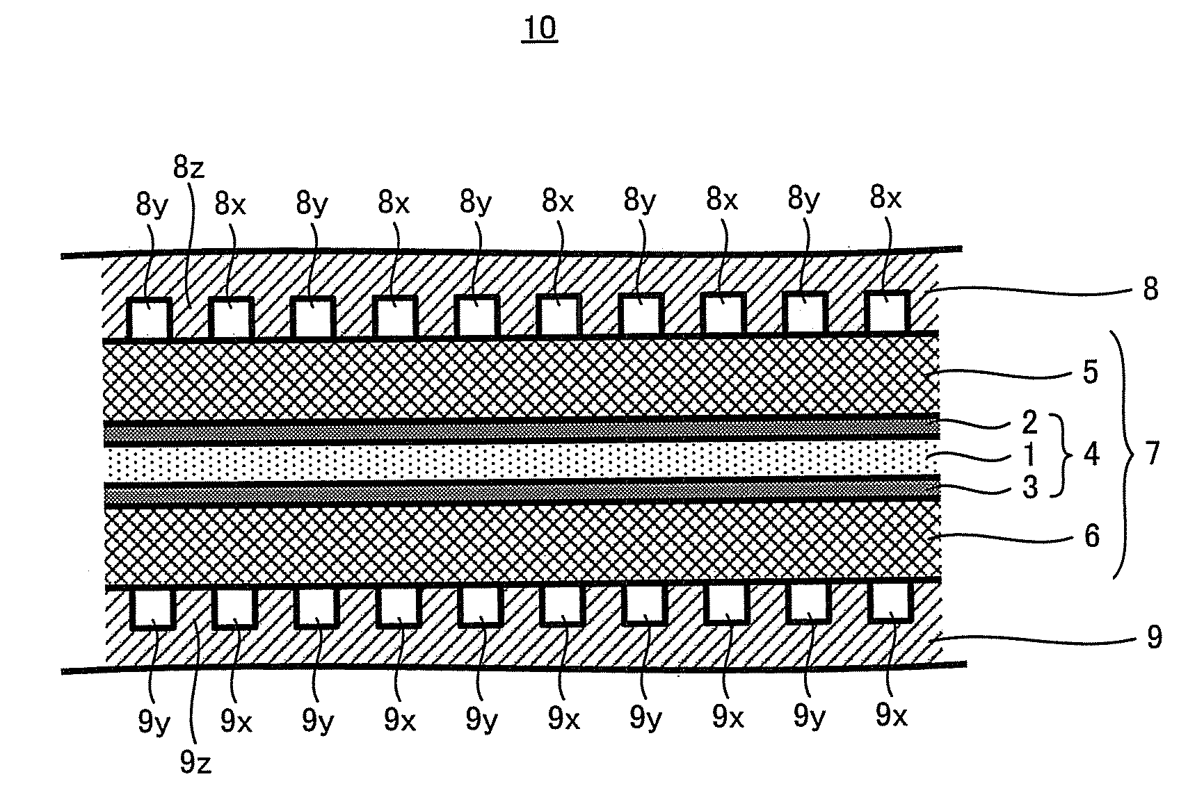
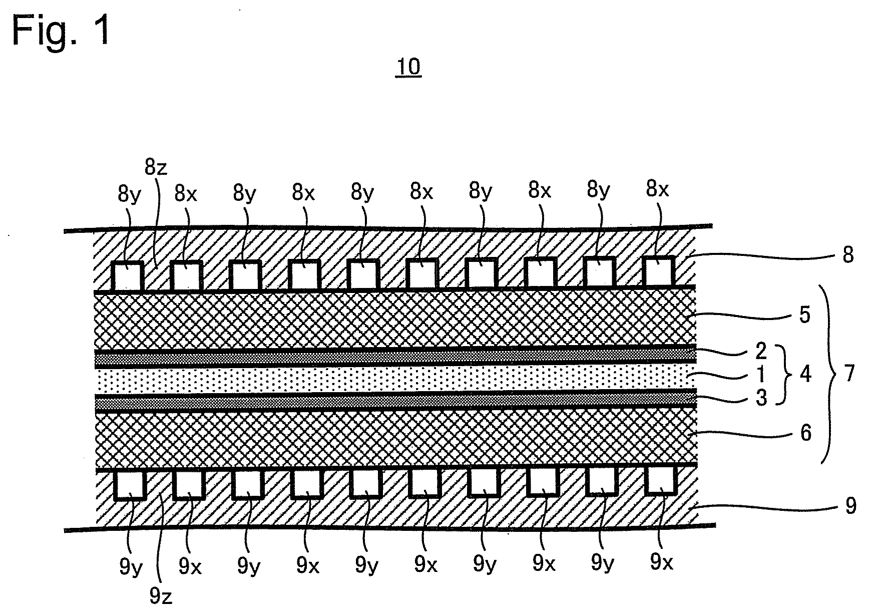
[0042]When operating PEFC, amount of water contained in the laminated body incorporating the MEA is different depending on the mode of the laminated body, structure of passage for hydrogen passing along the anode catalyst layer side, structure of passage for air passing along the cathode catalyst layer side, and operating condition; even in the surface of the anode catalyst layer and the cathode catalyst layer, mal-distribution of water can occur. Because of this, flooding is sometimes caused at a particular site in the surface due to the excessive water and other sites in the same surface cause desiccation due to the shortage of water. This phenomenon is attributed to the fact that, for example, the amount of water removed from the reaction gas differs depending on the site of the anode catalyst layer and the cathode catalyst layer.

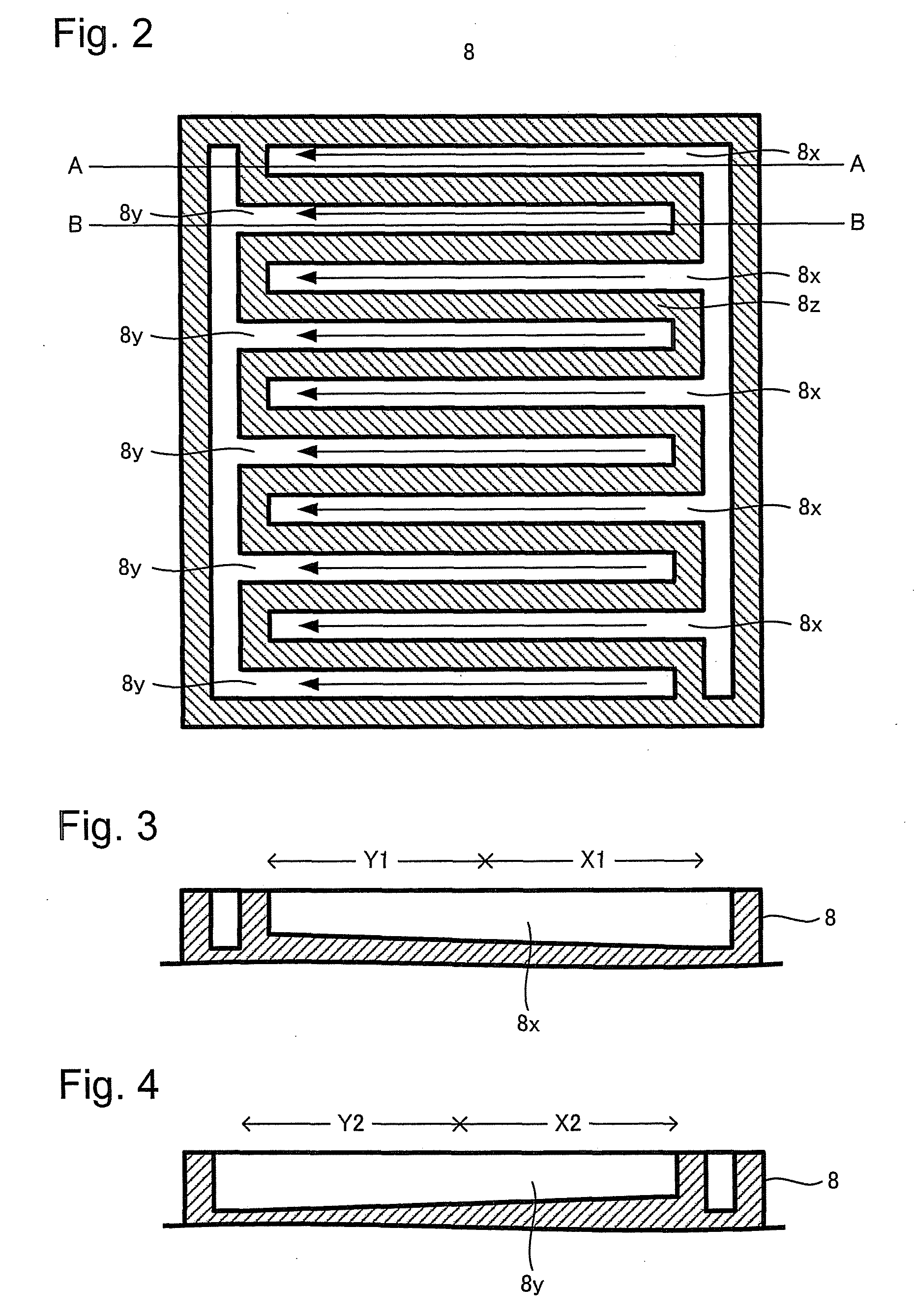
[0043]The present inventors discovered that there is a relation between the flow rate of the reaction gas and the amount of water removed by the reactio...


PUM

PropertyMeasurementUnit
depthaaaaaaaaaa
electrochemical reactionaaaaaaaaaa
electric energyaaaaaaaaaa

Abstract

The present invention provides a fuel cell having a blocked passage and showing capability of inhibiting desiccation and flooding of the membrane electrode assembly. The fuel cell comprises: a laminated body comprising at least a membrane electrode assembly which includes: an electrolyte membrane, an anode catalyst layer arranged on one surface of the electrolyte membrane, and a cathode catalyst layer arranged on the other surface of the electrolyte membrane; and a pair of separators sandwiching the laminated body, wherein, between the pair of separators, along the laminated body side surface of at least one separator, an inlet passage is provided for getting through a reaction gas supplied to the laminated body and an outlet passage is provided for getting through a reaction gas having passed through the laminated body; the inlet passage is blocked at a downstream end of the reaction gas being supplied to the laminated body and the outlet passage is blocked at an upstream end of the reaction gas having passed through the laminated body; the inlet passage and the outlet passage are arranged separately from each other along the separator; and the depth of the upstream region of the inlet passage is larger than that of the downstream region of the inlet passage.

Description

TECHNICAL FIELD[0001]The present invention relates to a fuel cell, particularly relates to a fuel cell having inlet passage or outlet passage either of which is blocked.BACKGROUND ART[0002]A fuel cell is an apparatus which produces electrochemical reaction at the membrane electrode assembly (hereinafter, refer to as “MEA”.) comprising: an electrolyte layer (hereinafter, refer to as “electrolyte membrane”.); and electrodes (an anode catalyst layer and a cathode catalyst layer) being disposed on each surface of the electrolyte membrane to take the electric energy generated by the electrochemical reaction out from the MEA. Among the fuel cells, a solid polymer electrolyte fuel cell (hereinafter, refer to as “PEFC”.) used for, e.g., household cogeneration system and automobiles can be operated in a low temperature region. Because of high energy conversion efficiency, short start-up time, and small-sized and lightweight system, the PEFC has attracted attention as a power source of batter...

Claims


Application Information

Patent Timeline
Patent Type & Authority Applications(United States)
IPC IPC(8): H01M8/10
CPCH01M8/0258Y02E60/50H01M2008/1095H01M8/0265H01M8/0267H01M8/0263H01M8/026
Inventor JOMORI, SHINJITAKEHIRO, NAOKIARAI, TATSUYAKANEKO, KEIICHITANIGUCHI, TAKUMI
Owner TOYOTA JIDOSHA KK
Why Eureka
Try Eureka