Switch mode voltage rectifier, RF energy conversion and wireless power supplies

a voltage rectifier and switch mode technology, applied in the field of voltage rectifiers, can solve the problems of critical design hurdles for power supply, inefficiency of conventional rectifiers used in wirelessly powered devices such as uhf rfids, micro-sensors and biomedical implants, and the threshold voltage of devices, etc., to achieve high operating efficiency, low turn-on voltage, and increase on-resistance

Inactive Publication Date: 2011-05-26
RGT UNIV OF CALIFORNIA
View PDF2 Cites 44 Cited by
  • Summary
  • Abstract
  • Description
  • Claims
  • Application Information

AI Technical Summary

Benefits of technology

[0009]Embodiments of the present invention provide cross-coupled rectifiers that use near zero-threshold transistors in a switching topology, but provide a topology that avoids reverse conduction problems. Importantly, preferred embodiment rectifiers of the invention only provide a slightly increased on-resistance in each branch, while providing both very high operating efficiency and very low turn-on voltage. An embodiment of the invention is a voltage rectifier for the conversion of RF energy into DC voltage with a turn-on threshold voltages approaching 0V.

Problems solved by technology

As wireless biomedical implant devices advance to smaller sizes with higher processing power, the issue of power supply becomes a critical design hurdle.
Unfortunately, as device (antenna) size decreases power collected by the device falls off in proportion to the mutual inductance squared or R4 where R is the radius of the antenna coil.
Conventional rectifies used in wirelessly powered devices such as UHF RFIDs, micro-sensors and biomedical implants are unfortunately extremely inefficient at low input levels.
The inefficiency arises from the threshold voltage (Vth) of devices used within the rectifier, which are generally standard CMOS transistors.
This method has the disadvantage of requiring an alternate power source to supply this canceling voltage, making a passive design impossible.
While this approach can provide high efficiencies at low input power levels, it still requires that DC power is generated by the rectifier before any cancellation can take place and therefore fails to address turn-on voltage.
A limitation of the charge pump diode design is that the rectifier's loss over the RF cycle is dependent upon the load.
6, As the output voltage increases, a DC offset voltage builds up at the devices gates (between VinRF and ground or VoutDC), this causes the devices to remain on during zero crossings in the RF input cycle leading to reverse conduction and power loss.

Method used


Image

  • Switch mode voltage rectifier, RF energy conversion and wireless power supplies
  • Switch mode voltage rectifier, RF energy conversion and wireless power supplies
  • Switch mode voltage rectifier, RF energy conversion and wireless power supplies

Examples


Embodiment Construction

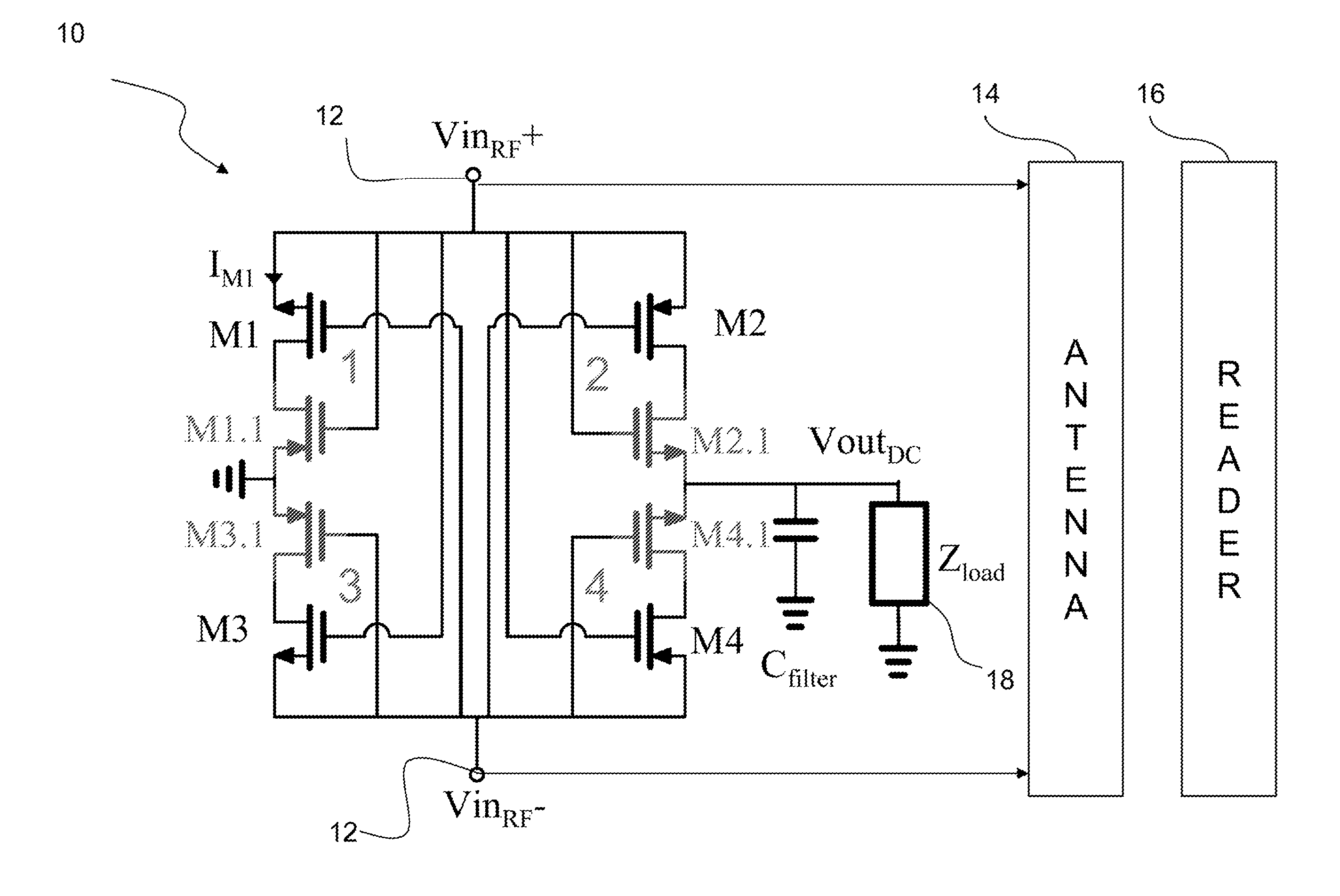
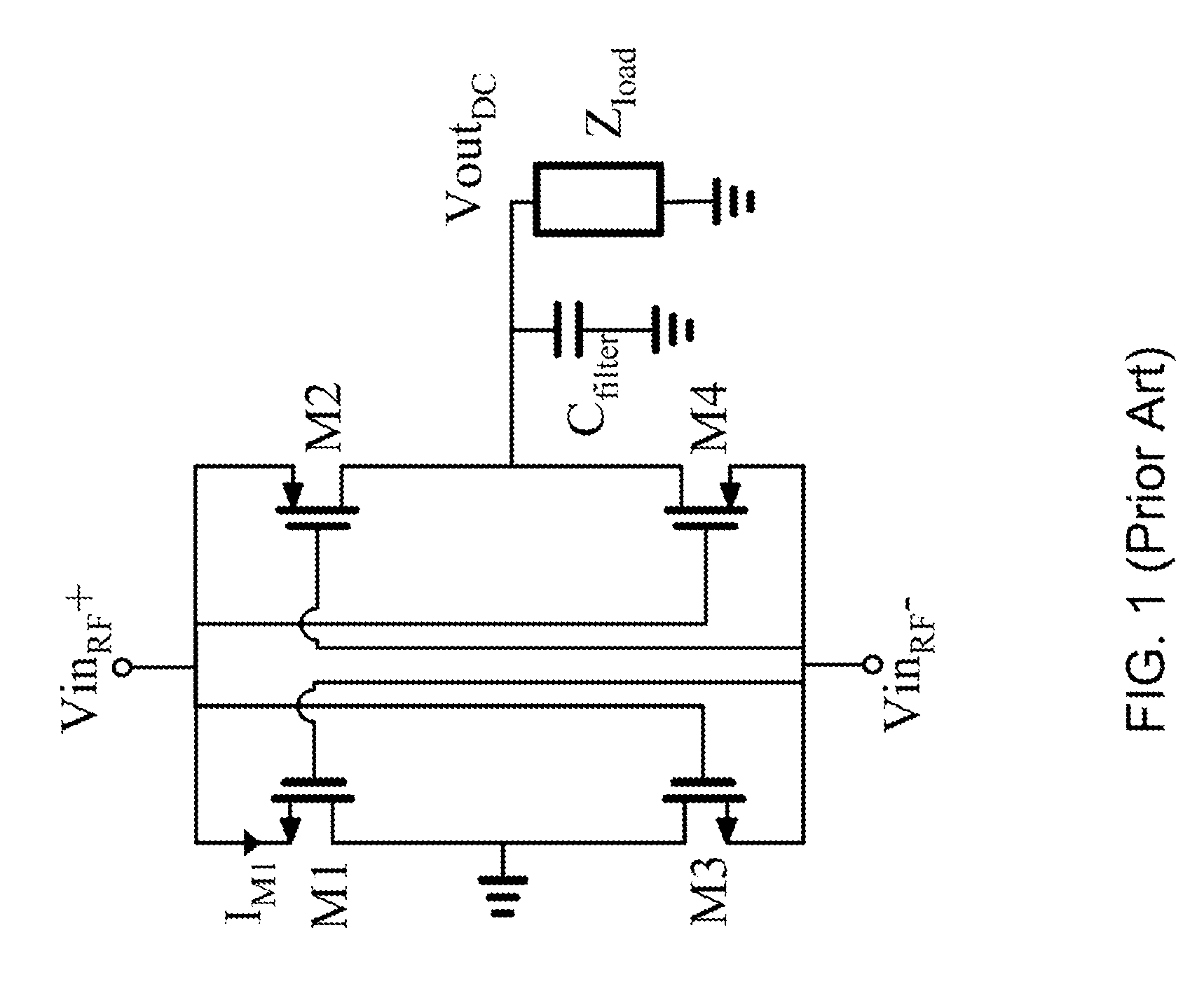
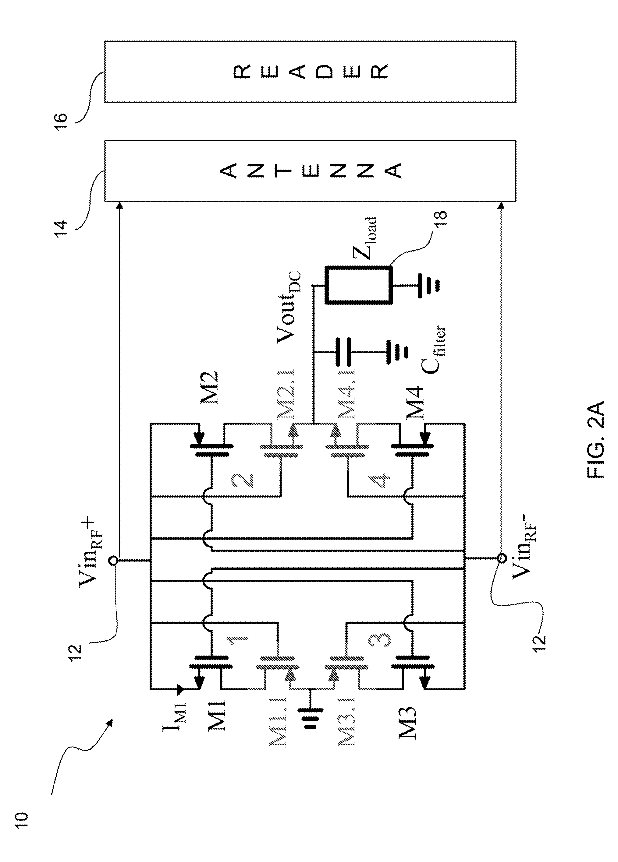
[0018]Embodiments of the present invention provide cross-coupled rectifiers that use near zero-threshold transistors, but provide a topology that avoids the reverse conduction problem that would arise if such transistors would be used in the topology of FIG. 1. Importantly, preferred embodiment rectifiers of the invention only provide a slightly increased on-resistance in each branch, while providing both very high operating efficiency and very low turn-on voltage. An embodiment of the invention is a voltage rectifier for the conversion of RF energy into DC voltage with a turn-on threshold voltages approaching 0V. State of the art devices require some minimum voltage application to activate the devices, typically a few hundred millivolts, rendering them insensitive to very small input values. Preferred embodiment voltage rectifiers provide response to very low power RF signals, and have many applications. An example application is a sensing device to monitor very small input values ...


PUM


Abstract

Embodiments of the present invention provide cross-coupled rectifiers that use near zero-threshold transistors in a switching topology, but provide a topology that avoids reverse conduction problems. Importantly, preferred embodiment rectifiers of the invention only provide a slightly increased on-resistance in each branch, while providing both very high operating efficiency and very low turn-on voltage. An embodiment of the invention is a voltage rectifier for the conversion of RF energy into DC voltage with a turn-on threshold voltages approaching 0V.

Description

CLAIM FOR PRIORITY AND REFERENCE TO RELATED APPLICATION[0001]This application claims priority under 35 U.S.C §119 from prior provisional application No. 61 / 262,282 which was filed on Nov. 18, 2010.FIELD[0002]A field of the invention is voltage rectifiers. Another field of the invention is RF energy conversion. Example applications of the invention include wireless sensors, wireless power supplies and wireless energy harvesting. Preferred particular applications of the invention include UHF RFID tags and wirelessly powered biomedical implant devices.BACKGROUND[0003]As wireless biomedical implant devices advance to smaller sizes with higher processing power, the issue of power supply becomes a critical design hurdle. Designers for biomedical devices have turned their attention to sensors that are powered by RF energy that is implanted on or within the skin. The most popular power transfer technique is inductive coupling (near-field) because attenuation in tissue is reduced in comparis...

Claims


Application Information

Patent Timeline
Patent Type & Authority Applications(United States)
IPC IPC(8): H04B1/16H02M7/217
CPCH02J5/005Y02B70/1408H02M2007/2195H02M7/219H02J50/20H02M7/2195Y02B70/10
Inventor THEILMANN, PAULASBECK, PETER
Owner RGT UNIV OF CALIFORNIA
Why Eureka
Try Eureka