Signal detecting device for detecting a difference signal for an electrical measurement of a vital parameter of a living being, electrode arrangement and method

a technology of electrical measurement and signal detection device, which is applied in the field of signal detection device for detecting a difference signal for an electrical measurement, can solve the problems of no system known on the market which is really able to record vital data, the ecgs recording of the electrocardiograph, and the build-up time of the sensors, so as to improve the continuous detection and increase the contact probability

Active Publication Date: 2011-05-26
FRAUNHOFER GESELLSCHAFT ZUR FOERDERUNG DER ANGEWANDTEN FORSCHUNG EV
View PDF14 Cites 37 Cited by
  • Summary
  • Abstract
  • Description
  • Claims
  • Application Information

AI Technical Summary

Benefits of technology

Consequently, one advantage of the present invention is that redundancy of electrodes contacting the body results from the plurality of electrodes and that that pair of electrodes which have the most suitable difference signal for measuring the vital parameter may be selected by the electrode selecting device.
Additionally, the present invention provides an electrode arrangement comprising a plurality of electrodes, the plurality of electrodes being arranged in a motorcar so as to contact the user, wherein at least one of the electrodes is arranged in an operating element of the motorcar and at least one other electrode is arranged in a rest element of the motorcar.
Subsequently, operating element also means a control element, such as, for example, a steering wheel or gear shift lever, or a switching element, such as, for example, a rotary switch of a radio or an indicator lever.
A “motorcar” will subsequently also be referred to as “MC” in short.
This aspect of the present invention is based on the finding that, when driving, an MC user will typically not have his hands located on operating element of the MC or the steering wheel permanently. Knowing that, when driving, an MC user will frequently have one of his hands located on an operating element, such as, for example, the steering wheel or gear lever of the MC, and another hand located on a rest element, such as, for example, an armrest area of the MC, there will be increased contacting probability and thus improved continuous detection for the electrical measurement of a vital parameter of the MC user, caused by the integration of at least one electrode in a rest element of the MC.
Thus, another advantage of the present invention is that electrode signals may even be provided when an MC user does not have both hands located on an operating element, such as, for example, the steering wheel.

Problems solved by technology

In contrast to body function monitoring devices which are also available for end users, such as, for example, pulse watches, electrocardiographs for recording ECGs are frequently operated by physicians only due to their complexity.
One disadvantage of many diagnostic methods for the cardiovascular system when being used under automobile conditions, but also in diagnostics, for example when seeing a physician, is that they are either of invasive character or that application parts thereof (electrodes and leads thereof) have to be applied to the body before measuring and be connected to signal evaluating electronics.
Most known systems for monitoring drivers by means of vital sensor technology (such as, for example, pulse measurements or ECG) are only described too generally and ignore important aspects such as: signal quality, coverage of the passenger area with sensors, probability and frequency of sensor contacts by the driver, diverting the driver by the interaction with the measuring system and potentially resulting impairment of driving safety, and build-up time of the sensors, i.e. how fast the sensors are able to provide valid data after being touched.
However, up to now there are no systems known on the market which are really able to record vital data in automobiles for diagnostics and therapy support with the precision needed.
This may be explained by the challenging fringe conditions and the lack of acceptance on the part of the driver (sensor on the body) in the automobile environment.

Method used


Image

  • Signal detecting device for detecting a difference signal for an electrical measurement of a vital parameter of a living being, electrode arrangement and method
  • Signal detecting device for detecting a difference signal for an electrical measurement of a vital parameter of a living being, electrode arrangement and method
  • Signal detecting device for detecting a difference signal for an electrical measurement of a vital parameter of a living being, electrode arrangement and method

Examples


first embodiment

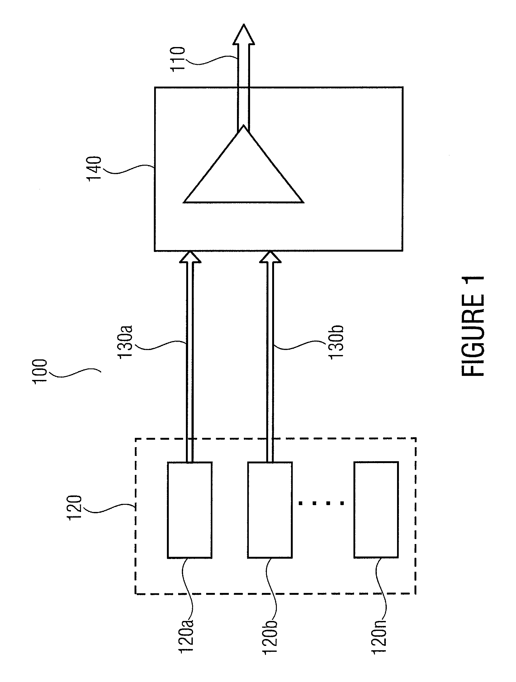
FIG. 1 shows a schematic illustration of a signal detecting device 100 in accordance with the present invention. The signal detecting device 100 for detecting a difference signal 110 for an electrical measurement of a vital parameter of a living being includes a plurality 120 of electrodes 120a-120n and an electrode selecting device 140. The electrodes 120a-120n are connected to the electrode selecting device 140 so as to provide electrode signals 130 to the electrode selecting device 140.

Electrodes 120a-120n from the plurality of electrodes can contact the living being and provide electrode signals 130 to the electrode selecting device 140. Based on, for example, the strength (or amplitude) of the electrode signals 130 (or another characteristic feature of the electrode signals 130, like, for example, an intensity and characteristic signal shape or a characteristic frequency portion) of the individual electrodes 120a-120n, the electrode selecting device 140 can select one pair of e...

second embodiment

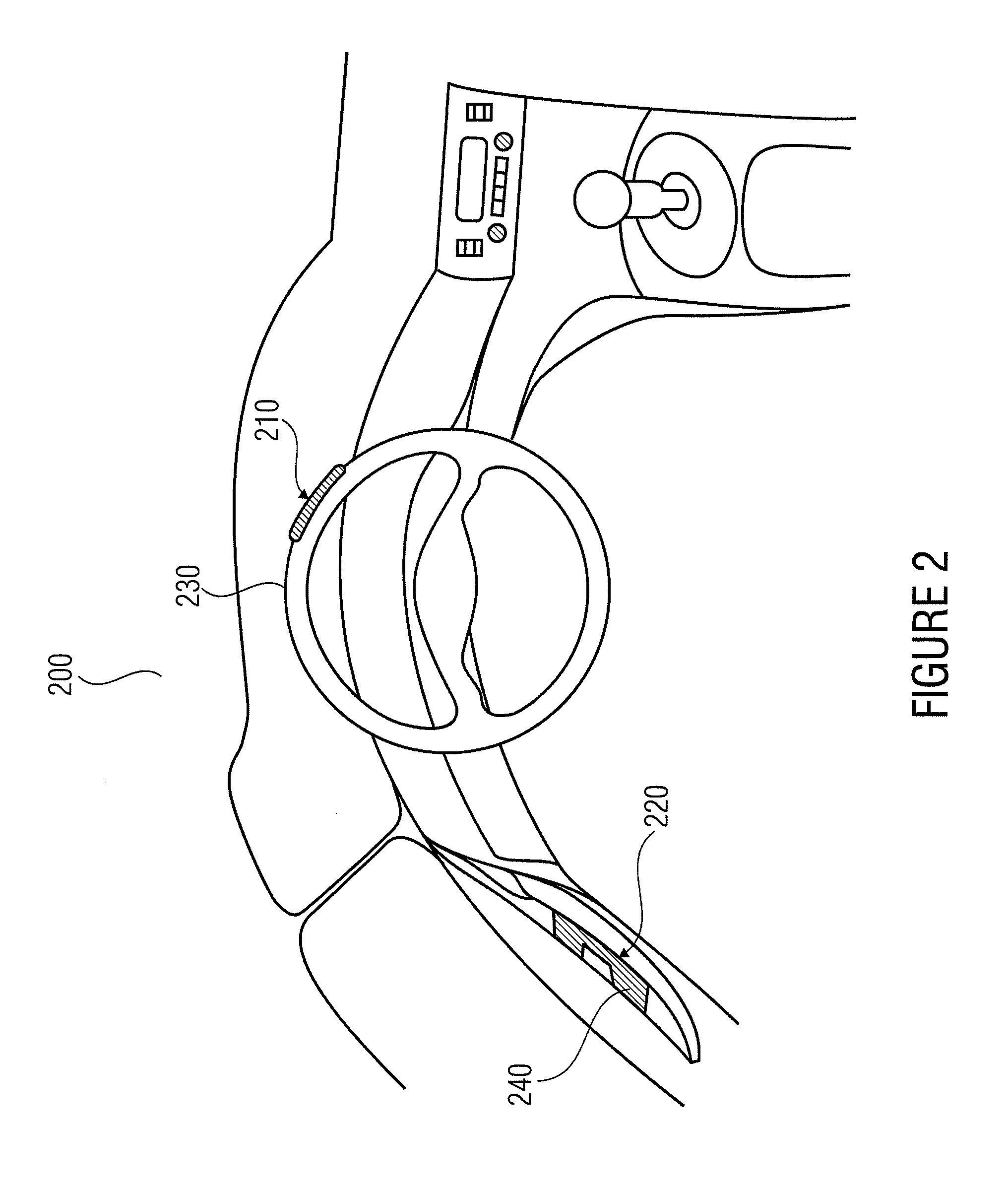
FIG. 2 shows a picture of an electrode arrangement 200 in accordance with the present invention. The electrode arrangement 200 is integrated in an MC, a first electrode 210 being applied in, at or on an operating element 230. A second electrode 220 is applied in, at or on a rest element 240 of the MC. The operating element 230 may exemplarily be a steering wheel of the MC, wherein the rest element 240 may exemplarily be an armrest area of the driver's door of the MC.

The first electrode 210 and the second electrode 220 are arranged in the MC such that they are able to contact the MC user (exemplarily when same is in a driving position). Exemplarily, the first electrode 210 may be arranged such that it contacts the right hand of the MC user and the second electrode 220 may be arranged such that it contacts the left hand of the MC user. The electrode arrangement 200 shown may thus be used to detect, for example, a difference signal for electrically measuring a vital parameter of the MC...

third embodiment

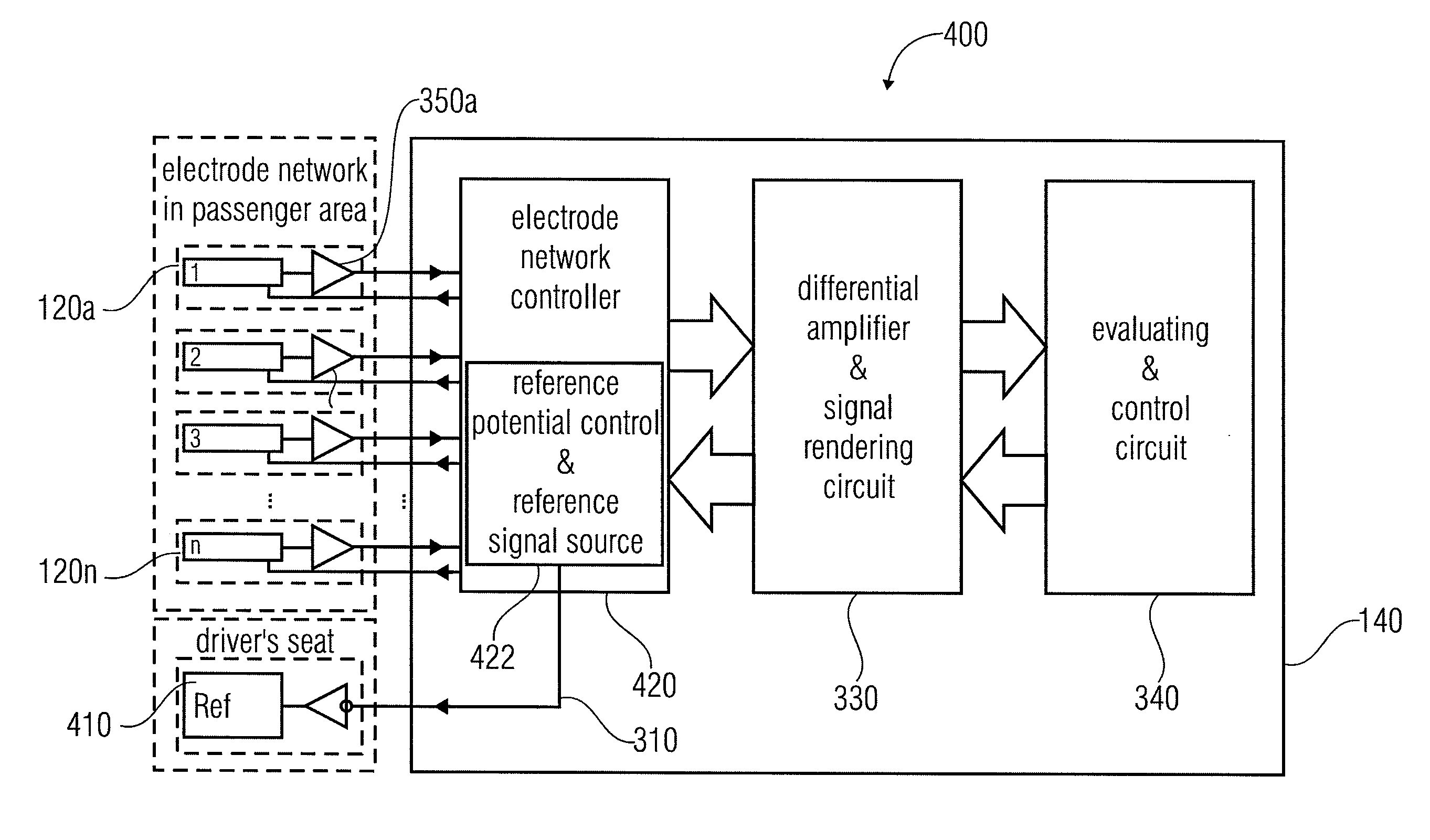
FIG. 3a shows a schematic illustration of a signal detecting device 300 in accordance with the present invention. The signal detecting device 300 includes a plurality of electrodes 120a-120n or electrode network 120. The electrode network 120 includes at least a first electrode 120a, a second electrode 120b and a third electrode 120c. The electrode network 120 may include any number of additional electrodes 120a-120n. In addition, the signal detecting device 300 includes an electrode selecting device 140. The electrode selecting device 140 includes an electrode network controller 320, a differential amplifier and signal rendering circuit 330 and an evaluating and control circuit 340. The electrode network controller 320 includes means 322 for capacitive signal coupling-in and capacitive reference potential driving including a reference signal source. In other words, FIG. 3a shows an exemplary integration of the signal detecting device 300 or the system for detecting the ECG by means...


PUM


Abstract

What is described are a signal detecting device for detecting a vital parameter of a living being, having a plurality of electrodes and an electrode selecting device for selecting a pair of electrodes from the plurality of electrodes such that a difference signal suitable for measuring the vital parameter is derivable, an electrode arrangement and a method.

Description

CROSS-REFERENCE TO RELATED APPLICATIONThis application claims priority from German Patent Application No. 10 2009 050 755.8, which was filed on Oct. 27, 2009, and is incorporated herein by reference in its entirety.BACKGROUND OF THE INVENTIONThe present invention relates to a signal detecting device for detecting a difference signal for an electrical measurement of a vital parameter of a living being, for example an ECG measurement, to an electrode arrangement as may exemplarily be arranged in a motorcar (MC), and to a method.The heart, being one of the most important organs of the human organism, represents a broad basis for diagnosing most different diseases in medicine. Electrical potentials form on the body's surface caused by the three-dimensional propagation of the excitation in the heart. Detecting temporal changes of potential differences between defined positions on the body's surface is referred to as electrocardiography. The recording of the potential lines resulting is r...

Claims


Application Information

Patent Timeline
Patent Type & Authority Applications(United States)
IPC IPC(8): A61B5/04A61B5/308
CPCA61B5/0245A61B5/18A61B5/0428A61B5/30A61B5/308A61B5/305
Inventor ERSHOV, SERGEYMOERSDORF, HANS-JOACHIMRYBALKO, RUSLANCOURONNE, ROBERT
Owner FRAUNHOFER GESELLSCHAFT ZUR FOERDERUNG DER ANGEWANDTEN FORSCHUNG EV
Why Eureka
Try Eureka