[0010]One embodiment of the present invention may be designed specifically for ground vehicle defense against RPGs (
rocket propelled grenades). Such an embodiment of the invention may not require exquisite accuracy in
azimuth and elevation but may require an accuracy of plus or minus three feet in the range measurement by the
radar in order to trigger any appropriate countermeasures accurately. Appropriate countermeasures may include non-lethal shot projectors that throw shot in a wide pattern to intercept and destroy or detonate an incoming RPG. An embodiment of the present invention may also determine an expected
impact location relative to the vehicle carrying the inventive system for more accurate and effective countermeasures deployment.
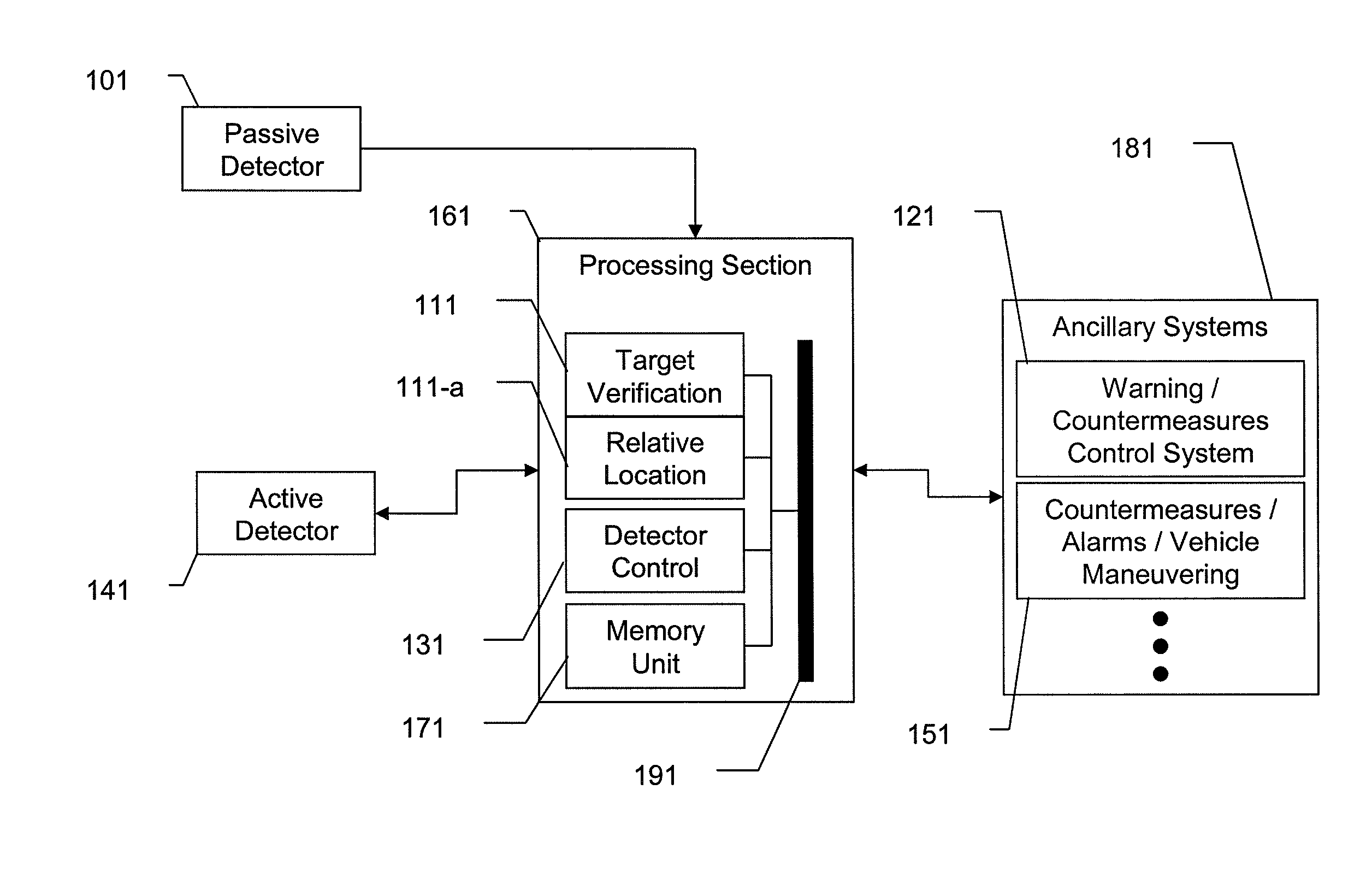
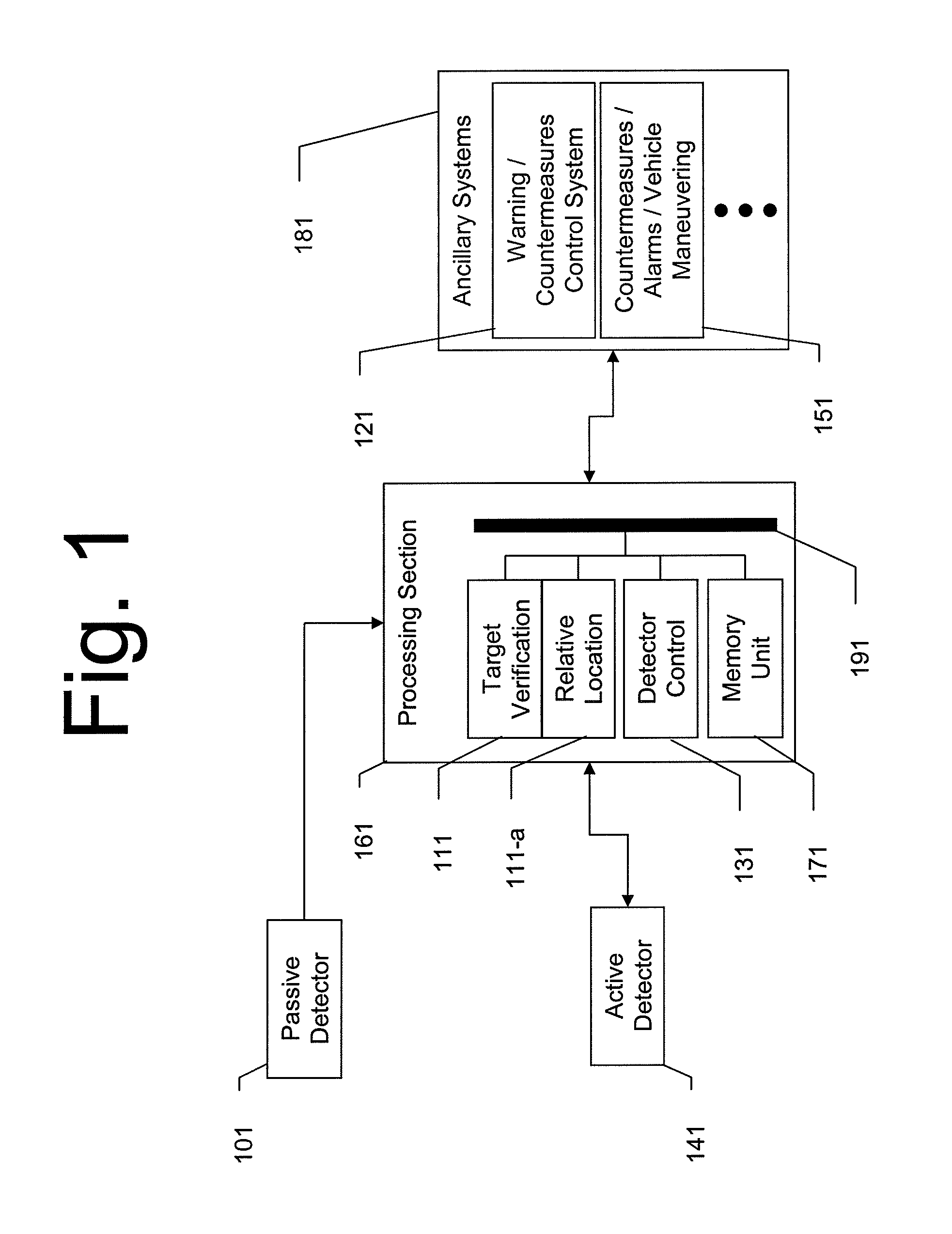
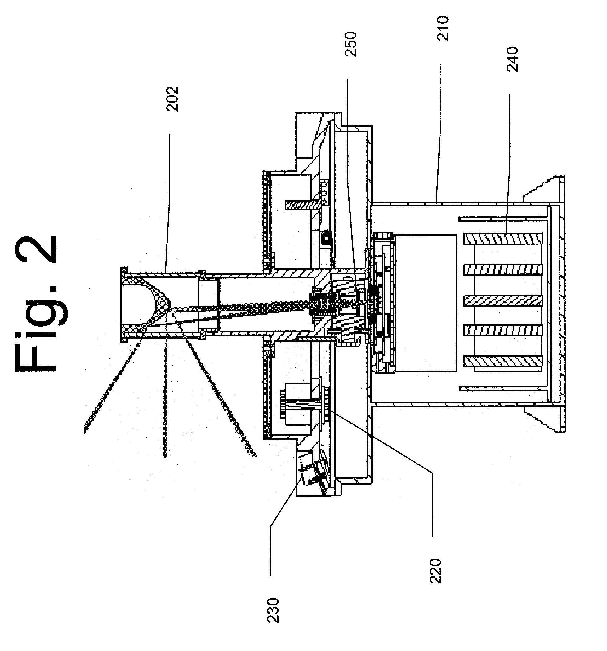
[0011]A
sensor system according to the present invention configured for the above inventive embodiment may include an optical
sensor system surrounded by a radar
sensor system, with both systems potentially sharing a common set of electronic components. In one such embodiment, both systems may have a 360 by 60 degree
field of view. Alternate embodiments of the present invention may have different fields of view depending on their specific application or configuration needs. One potential alternative embodiment may be an optical system with a 360 by 120
field of view and two separate range-finding systems, each with a non-overlapping 360 by 60 degree
field of view. In yet further alternative embodiments, the field of view and configuration of the initial detection and
ranging portions may be reversed or otherwise configured based on the operating and deployment requirements of the system. In embodiments where the detection and
ranging systems operate on different technologies (i.e.
millimeter-wave and
sonar), it may be advantageous to use fewer shared components. In embodiments where the system is expected to be subject to damage from environmental or other factors, it may be advantageous to include redundant or otherwise fault-tolerant components in either or both sensors and / or in the
electronics,
[0012]By combining detection and
ranging sensors into a single system, embodiments of the present invention provide a number of advantages. In the radar and optical embodiment, both optical and
radar systems produce false alarms. By requiring both an optical signature and radar signature together to identify a threat, the present invention reduces the
false alarm rate to near zero.
Radar only systems must transmit continuously to detect threats. The radar
signal can be detected and the vehicle attacked. In addition, the constant radar emissions can create
radiation hazards to nearby humans if they are exposed for a significant period of time. This embodiment of the inventive device is passive until a potential threat is optically identified. Only then is the radar activated and then only for the period of time needed to detect the threat.
[0013]The use of multiple, distinct detection bands in the present invention improves the detection of threats. All band signatures are required to confirm an
attack. This feature is what reduces the
false alarm rate. Further, by having at least one of the bands configured for
passive detection and at least one band for
active detection and only engaging the
active detection system in response to a target acquired by the
passive detection system, the present invention realizes the benefits of an active detection system while preventing others from easily or readily identifying the source of the active detection system. Embodiments of the present invention therefore provide accurate detection of potential threats or targets with a low
false alarm rate.
[0014]Embodiments of the present invention also allow for a sensor system that realizes the benefits of an active detection paradigm while mitigating some of the downsides of that paradigm (specifically, reducing chances of detection and location of the active system by engaging active detection only for short periods and only after detection of a target or threat by the passive system).

