Clad metal substrates in optical packages

a technology of optical packaging and metal substrates, which is applied in the direction of optical elements, semiconductor lasers, instruments, etc., can solve the problems particularly challenging objects, etc., and achieves the effect of increasing overall package volume and operational complexity, and enhancing mechanical stability

Inactive Publication Date: 2011-06-02
CORNING INC
View PDF11 Cites 0 Cited by
  • Summary
  • Abstract
  • Description
  • Claims
  • Application Information

AI Technical Summary

Benefits of technology

[0003]The present inventors have recognized that frequency-converted laser sources and multi-color laser projectors must be compact to be feasible for many projection applications. This object is particularly challenging in multi-color projection systems requiring three independent color sources (red, green, blue). Although red and blue sources are reasonably compact, frequency-converted green laser sources present a particular challenge in this respect because they commonly utilize an IR laser source and a second harmonic generation (SHG) crystal or some other type of wavelength conversion device. Active or passive coupling optics are often utilized to ensure proper alignment of the IR pump light with the waveguide of the SHG crystal. The package may also include hardware for enhancing mechanical stability over a wide temperature range. Together, these components increase overall package volume and operational complexity.

Problems solved by technology

This object is particularly challenging in multi-color projection systems requiring three independent color sources (red, green, blue).
Although red and blue sources are reasonably compact, frequency-converted green laser sources present a particular challenge in this respect because they commonly utilize an IR laser source and a second harmonic generation (SHG) crystal or some other type of wavelength conversion device.
Together, these components increase overall package volume and operational complexity.

Method used


Image

  • Clad metal substrates in optical packages
  • Clad metal substrates in optical packages
  • Clad metal substrates in optical packages

Examples


Embodiment Construction

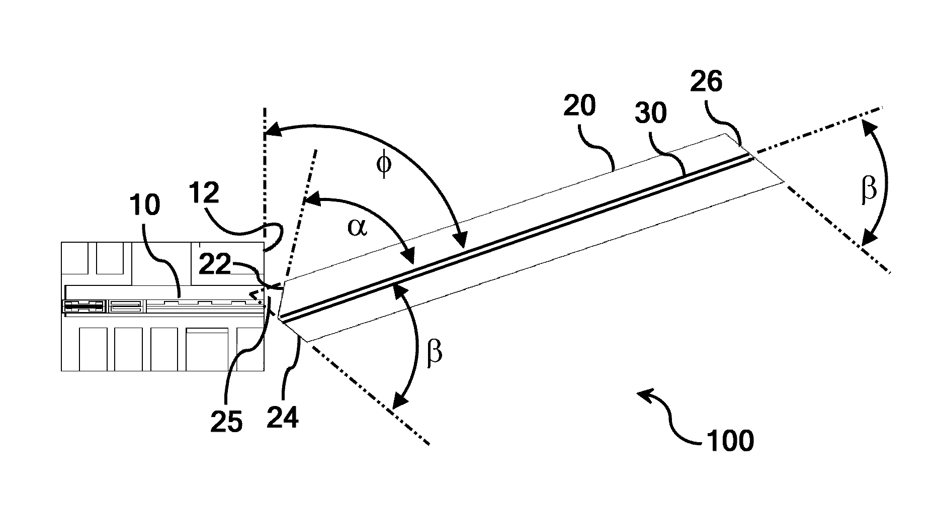
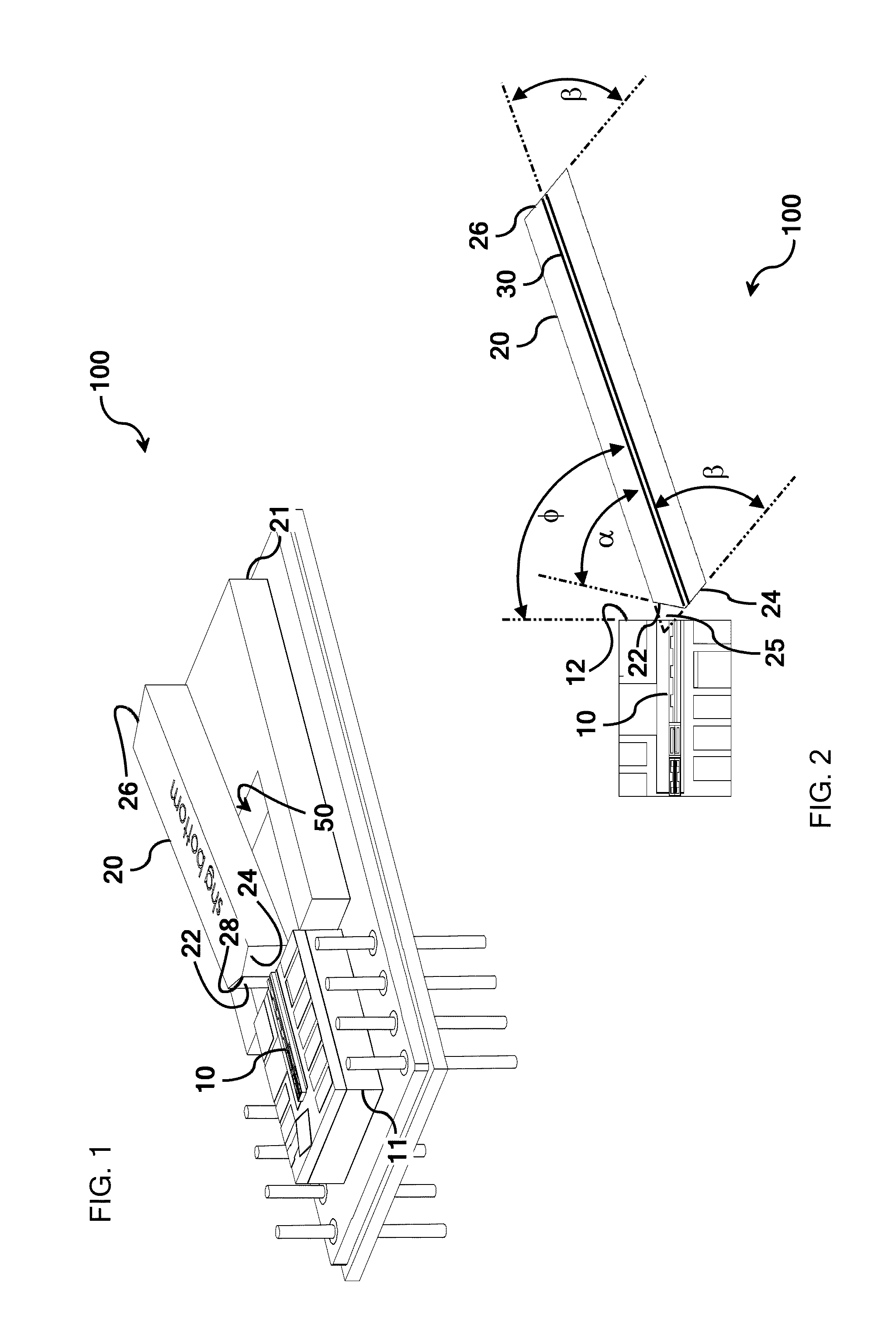
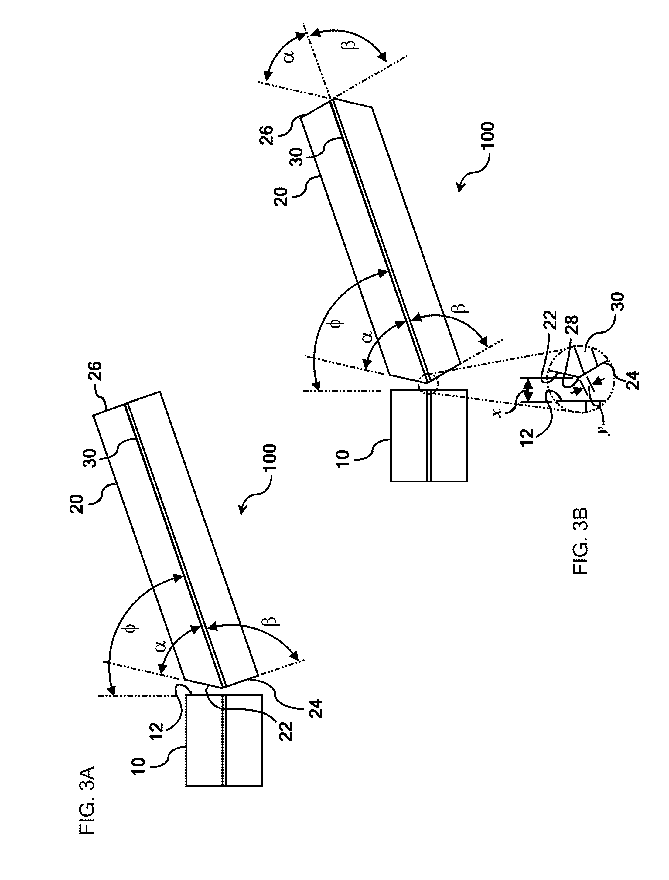
[0013]Referring initially to FIG. 1 and FIG. 2, an optical package 100 according to one embodiment of the present disclosure is illustrated. FIG. 1 illustrates an optical package 100 comprising a laser source 10 and a wavelength conversion device 20. The wavelength conversion device 20 comprises an input face formed of an α-cut facet 22 and β-cut facet 24, an output face 26, and a waveguide 30 extending from the input face to the output face 26. The laser source 10 is positioned such that an output face 12 of the laser source 10 is proximity-coupled to the waveguide portion of the input face of the wavelength conversion device 20.

[0014]For the purposes of describing and defining the present disclosure, it is noted that a laser source can be considered to be “proximity-coupled” to a wavelength conversion device when the proximity of the output face of the laser source and the input face of the wavelength conversion device is the primary mechanism for coupling an optical signal from t...


PUM


Abstract

Embodiments of the present disclosure bring a wavelength conversion device into close proximity with a laser source to eliminate the need for coupling optics, reduce the number of package components, and reduce package volume. According to one embodiment of the present disclosure, an optical package is provided comprising a laser diode chip and a clad metal substrate. The clad metal substrate comprises a clad metal region that is mechanically coupled to a base metal region. The laser diode chip is coupled to the clad metal region. The clad metal region comprises a clad metal material having a thermal conductivity that is greater than a thermal conductivity of the base metal material. The clad metal region further comprises a coefficient of thermal expansion that is approximately equal to a coefficient of thermal expansion of the base metal material and is greater than a coefficient of thermal expansion of the laser diode chip.

Description

CROSS-REFERENCE TO RELATED APPLICATIONS[0001]This application is related to U.S. patent application Ser. No. 12 / 471,681 filed May 26, 2009 and to U.S. patent application Ser. No. 12 / 471,666, filed May 26, 2009, but does not claim priority thereto.BACKGROUND[0002]The present disclosure relates to frequency-converted laser sources, laser projection systems and, more particularly, to optical packaging configurations for laser sources and multi-color laser projectors in applications such as cell phones, PDAs, laptop computers, etc.BRIEF SUMMARY[0003]The present inventors have recognized that frequency-converted laser sources and multi-color laser projectors must be compact to be feasible for many projection applications. This object is particularly challenging in multi-color projection systems requiring three independent color sources (red, green, blue). Although red and blue sources are reasonably compact, frequency-converted green laser sources present a particular challenge in this r...

Claims


Application Information

Patent Timeline
Patent Type & Authority Applications(United States)
IPC IPC(8): G02B6/36
CPCH01S5/0092H01S5/02208H01S5/0228H01S5/02272H01S5/02476H01S5/02248H01S5/0225H01S5/0237H01S5/02325
Inventor BHAGAVATULA, VENKATA ADISESHAIAHCHAPARALA, SATISH CHANDRAHIMMELREICH, JOHNHUGHES, JR., LAWRENCE CHARLES
Owner CORNING INC
Why Eureka
Try Eureka