Cathodic protection monitoring

Active Publication Date: 2011-06-02
BAKER HUGHES ENERGY TECH UK LTD
View PDF3 Cites 4 Cited by
  • Summary
  • Abstract
  • Description
  • Claims
  • Application Information

AI Technical Summary

Benefits of technology

[0012]The present invention thereby provides, inter alia, the following advantages: instantaneous and real-time monitoring of the level of CP is achievable, the invention may be fitted to otherwise standard underwater equi

Problems solved by technology

This is a cost and time-intensive procedure, especi

Method used


Image

  • Cathodic protection monitoring
  • Cathodic protection monitoring

Examples


Embodiment Construction

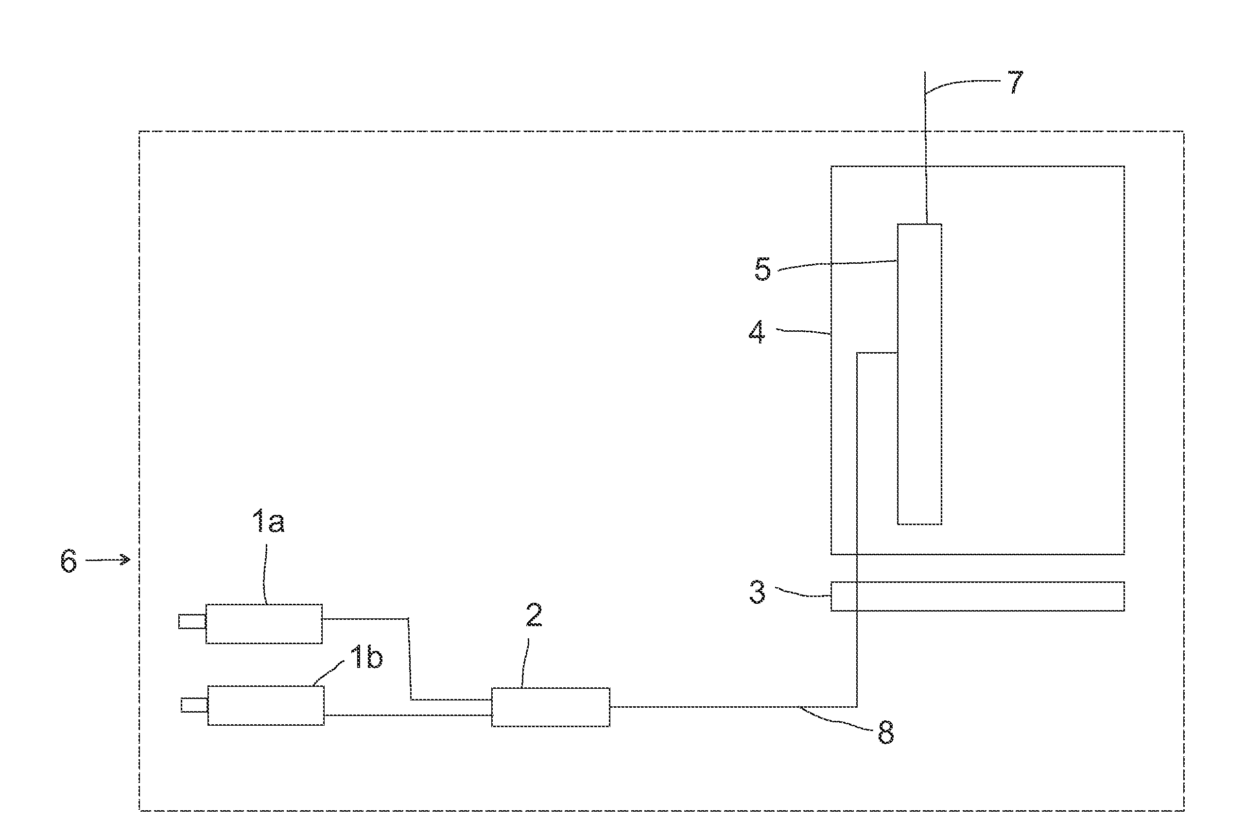
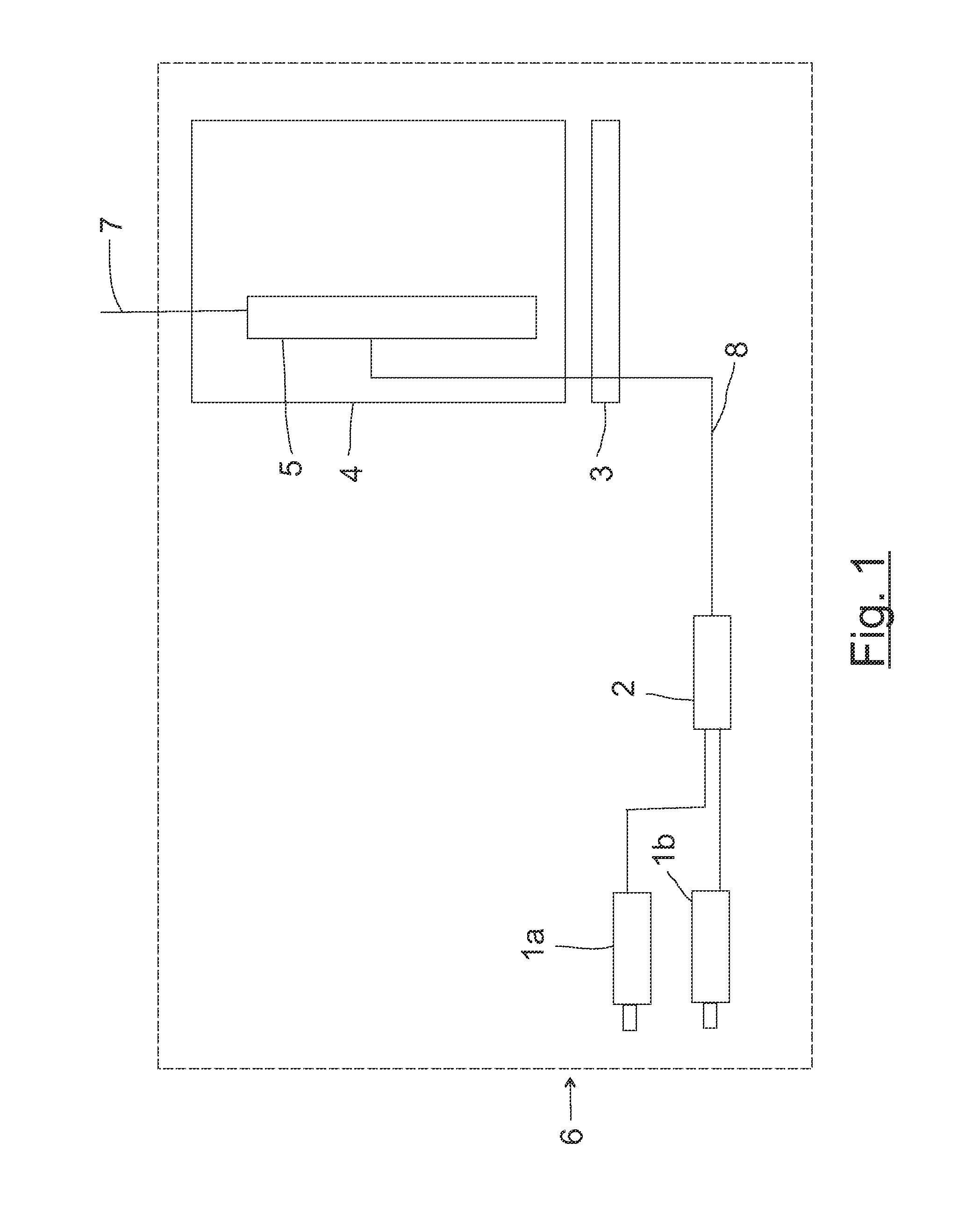
[0015]A pair of reference electrodes 1a and 1b are fitted to the structure, such that the first electrode 1a is electrically connected to the item to be protected, and the second electrode is positioned in contact with the water proximate the item. Here, the term “proximate” is used to denote water which is close enough to the item to enable a useful CP indication to be obtained, such distances being known in the art. These electrodes enable the measurement of the electrical potential (known as the “CP potential”) between the item and the surrounding seawater. The electrodes 1a, 1b may for example be zinc-based, or other materials as is known in the art, e.g. silver chloride. An electrical signal indicative of the cathodic protection level is thereby produced by the electrodes.

[0016]The potential is fed to a transducer 2, containing electronics, which converts the potential to a 4-20 mA interface. This interface can be any communications format, for example CANbus, Profibus or Modbu...


PUM


Abstract

A method of monitoring cathodic protection of an item located underwater at a facility, the facility further including a processing means, comprises the steps of providing a pair of first and second electrodes, the first electrode being electrically connected to the item and the second electrode being in contact with water proximate the item, measuring the potential between the first and second electrodes, producing an electrical signal indicative of the cathodic protection level, converting the signal into a communications format compatible with the processing means and passing it to the processing means, and transmitting the converted signal from the processing means to a surface location.

Description

BACKGROUND OF THE INVENTION[0001]1. Field of the Invention[0002]The present invention relates to a method of monitoring cathodic protection of an item located underwater at a facility and an underwater facility having an item requiring cathodic protection. In particular the invention is suitable for subsea hydrocarbon extraction facilities.[0003]2. Description of Related Art[0004]Metal items and surfaces which are deployed underwater, particularly subsea, are prone to corrosion, due to the electrolytic nature of the surrounding liquid. Such corrosion may result in underwater equipment failures with consequently significant costs of downtime and replacement.[0005]A standard technique for reducing corrosion after deployment of underwater equipment is to use cathodic protection, commonly abbreviated to “CP”. A widely-used form of CP is “galvanic anode CP”, in which a sacrificial metal surface is positioned proximate to the metal item to be protected. A sacrificial metal material is cho...

Claims


Application Information

Patent Timeline
IPC IPC(8): E02D31/06
CPCC23F13/04C23F2213/31C23F13/22C23F13/02G01N17/04
Inventor GUO, JUNXIANGLAKIN, JONATHANOKWUN-KALU, NNANNA KALU
Owner BAKER HUGHES ENERGY TECH UK LTD
Why Eureka
Try Eureka