
Hole diameter measuring method and device for holey optical fiber, and manufacturing method and device for holey optical fiber

a manufacturing method and optical fiber technology, applied in the direction of material analysis using wave/particle radiation, manufacturing tools, instruments, etc., can solve the problems of easy damage to optical fibers, difficult analysis of hole diameter, and large variation of interference patterns, so as to achieve the measurement of the hole diameter of a holey optical fiber, no risk of damage to the optical fiber, and no adverse effects on productivity

Inactive Publication Date: 2011-06-09
THE FUJIKURA CABLE WORKS LTD
View PDF20 Cites 5 Cited by
  • Summary
  • Abstract
  • Description
  • Claims
  • Application Information

AI Technical Summary

Benefits of technology

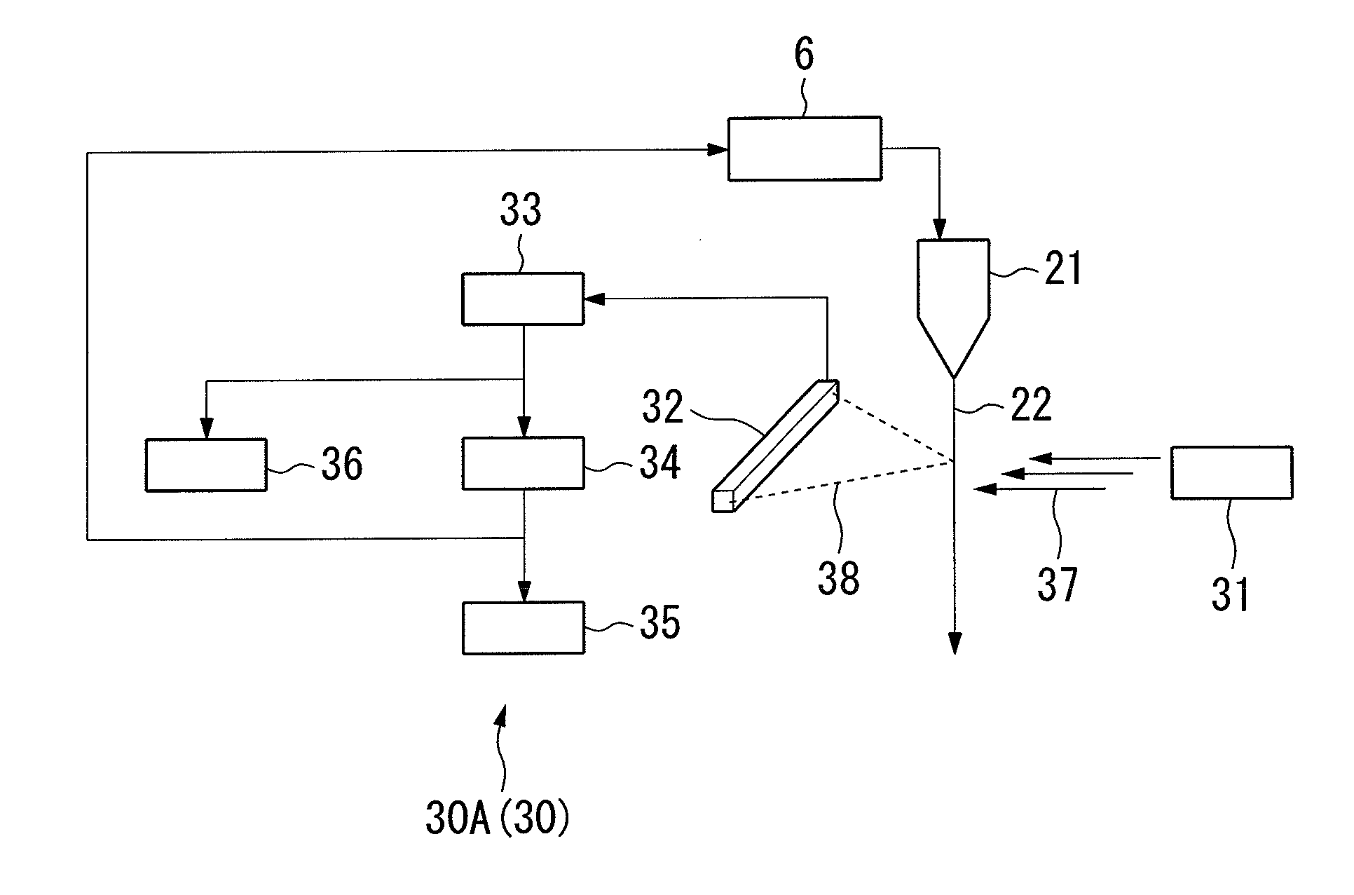
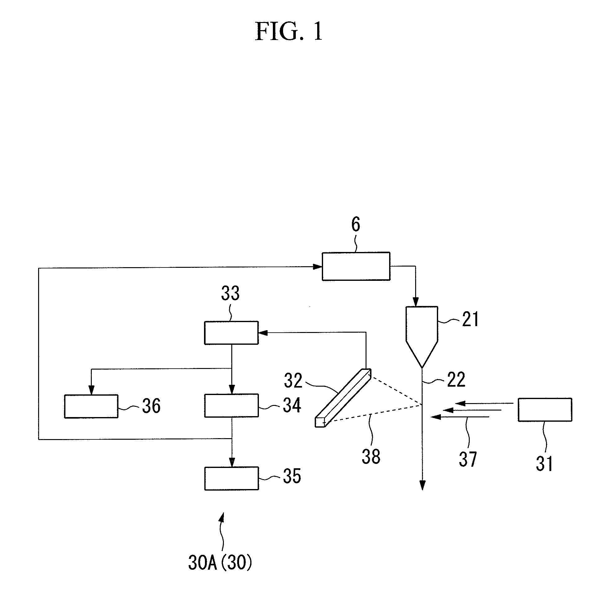
In the hole diameter measuring method for a holey optical fiber according to (1) above, parallel light rays are continuously irradiated from a side of the holey optical fiber bare wire, and the hole diameter is calculated based on the light amount of the forward scattering light that is generated by this irradiation. For this reason, it is possible to measure the hole diameter of a holey optical fiber without adding bending or the like to the optical fiber. As a result, there is no risk of causing damage to the optical fiber, and productivity is not adversely affected. Also, in the hole diameter measuring method for a holey optical fiber according to (1) above, the hole diameter is computed using a correlation relationship of a scattering intensity pattern of the forward scattering light and the hole diameter. For that reason, it is possible to accurately measure the hole diameter even in the case of a plurality of holes existing. In particular, in the hole diameter measuring method for a holey optical fiber according to (1) above, it is possible to measure the hole diameter in-line. For that reason, it is possible to reduce variations in the hole diameter, and possible to ensure the optical characteristics over the entire length of the manufactured optical fiber.

Problems solved by technology

Therefore, in the method of analyzing an interference pattern such as the method disclosed in Patent Document 1, the interference pattern becomes a complicated shape due to the plurality of holes.
As a result, the analysis of the diameter of a hole becomes difficult.
Moreover, in this method, the interference pattern changes greatly depending on the direction in which the light is irradiated.
For that reason, irradiation of laser diode light always from the same direction to the optical fiber is difficult to perform in reality.
Also, since it is necessary to impart a bend, the productivity of the optical fiber drops.
Furthermore, there is also a problem of this method only being applicable to a holey optical fiber in which the dependency of the bending loss on the hole diameter is large.

Method used


Image

  • Hole diameter measuring method and device for holey optical fiber, and manufacturing method and device for holey optical fiber
  • Hole diameter measuring method and device for holey optical fiber, and manufacturing method and device for holey optical fiber
  • Hole diameter measuring method and device for holey optical fiber, and manufacturing method and device for holey optical fiber

Examples


first embodiment

Hole Diameter Measuring Device for a Holey Optical Fiber and Holey Optical Fiber Manufacturing Device

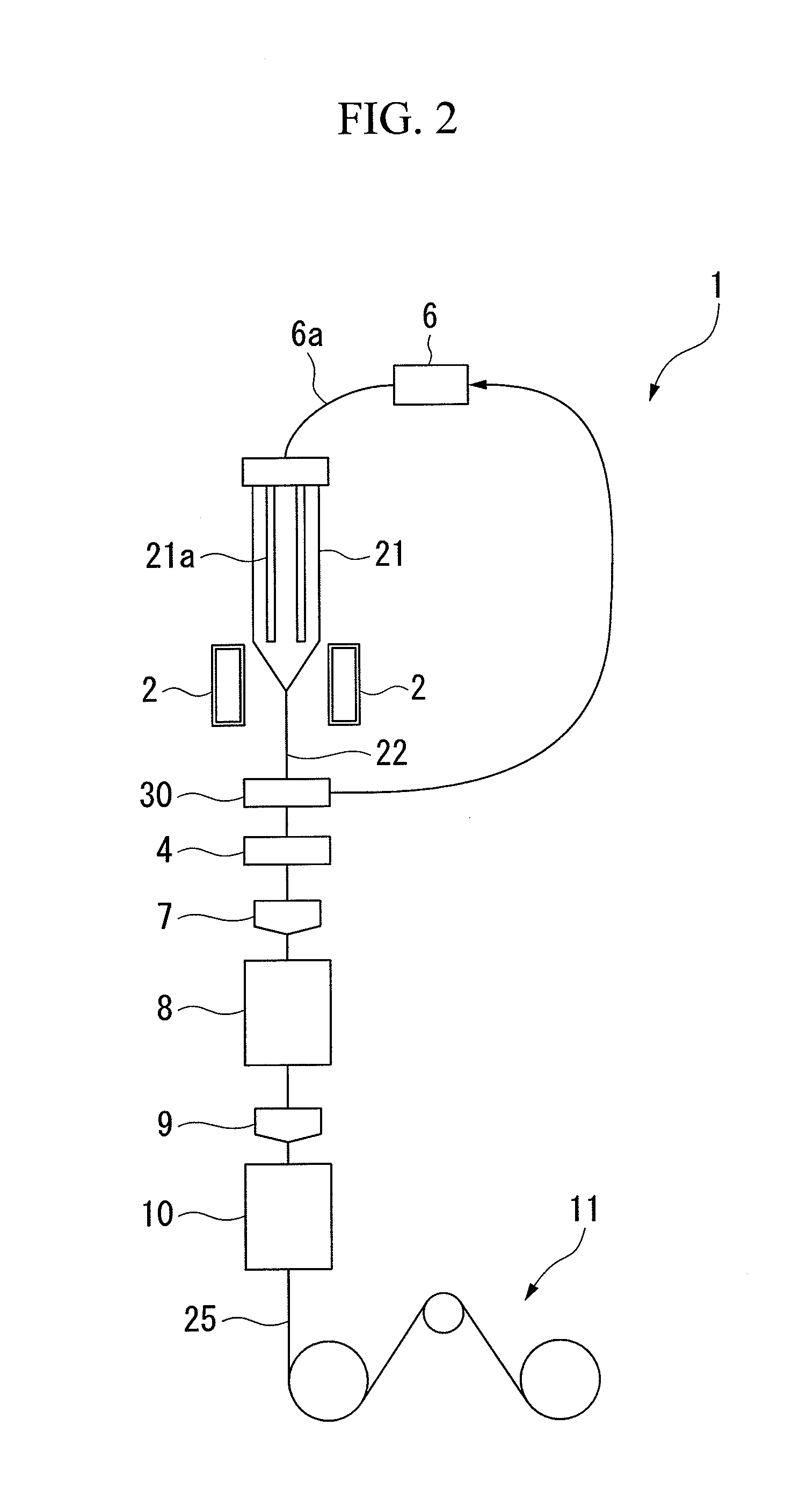
Hereinbelow, a hole diameter measuring device for a holey optical fiber and a holey optical fiber manufacturing device according to the first embodiment of the present invention shall be described in detail referring to the drawings. FIG. 1 is a schematic configuration drawing that shows a hole diameter measuring device 30A (30) for a holey optical fiber according to the first embodiment of the present invention (hereinbelow simply referred to as a hole diameter measuring device). FIG. 2 is a schematic configuration drawing that shows a holey optical fiber manufacturing device 1 according to one embodiment of the present invention (hereinbelow simply referred to as an optical fiber manufacturing device). The optical fiber manufacturing device 1 of the present embodiment is provided with the hole diameter measuring device 30A shown in FIG. 1, and the manufacturing method for a holey o...

second embodiment

FIG. 9C is a drawing that shows an example of a scattering intensity pattern that is obtained by the hole diameter measuring method of a holey optical fiber according to the second embodiment of the present invention.

The hole diameter measuring method of the present embodiment differs from the hole diameter measuring method of the first embodiment on the point of finding the width W of the central dark portion using the difference spectrum of the scattering intensity pattern that is obtained with a holey optical fiber and the scattering intensity pattern that is obtained with an optical fiber having no holes.

Note that when manufacturing a holey optical fiber, it is the same as that of the above-mentioned first embodiment besides finding the width W of the central dark portion using a difference spectrum. At this time, in the computing portion 34 in the hole diameter measuring device 30, it is programmed so that the width W of central dark portion is found using the difference spectr...

third embodiment

FIG. 10 is a drawing that schematically shows a hole diameter measuring device 30B (30) that is used for performing the hole diameter measurement method of the third embodiment of the present invention. The hole diameter measuring device 30B of the present embodiment differs from the first embodiment on the point of a plurality of irradiating devices 31 (31A, 31B) and detecting portions 32 (32A and 32B) being provided. These detecting portions 32A and 32B are connected to the same signal processing portion 33. The drawing shows the case of two of the irradiating devices 31 and the detecting portions 32 being provided, respectively, but they are not particularly limited to this number.

In the hole diameter measuring method of the aforementioned first embodiment (the hole diameter measuring device 30A), the width W of the central dark portion of the scattering intensity pattern 43 may end up changing due to the direction in which the parallel light rays 37 are irradiated. FIG. 11 is a ...


PUM

PropertyMeasurementUnit
Diameteraaaaaaaaaa
Diameteraaaaaaaaaa
Diameteraaaaaaaaaa

Abstract

A hole diameter measuring method for a holey optical fiber of the present invention is a hole diameter measuring method for a holey optical fiber having: continuously irradiating a side of a holey optical fiber bare wire with parallel light rays, the holey optical fiber bare wire obtained by drawing an optical fiber base material; continuously detecting, with a detecting portion, forward scattering light that is generated by the irradiation of the holey optical fiber bare wire with the parallel light rays; and calculating a diameter of at least one hole in the holey optical fiber bare wire using a correlation relationship between a scattering intensity pattern of the detected forward scattering light and the diameter of the at least one hole.

Description

TECHNICAL FIELDThe present invention relates to a hole diameter measuring method and device for a holey optical fiber in which a plurality of holes are formed in silica glass that constitutes an optical fiber, and to a manufacturing method and device for a holey optical fiber that uses this method and device.BACKGROUND ARTIn a holey optical fiber, a plurality of holes are formed along the lengthwise direction of the optical fiber in silica glass that constitutes an optical fiber. Such an optical fiber is called a photonic crystal fiber (PCF). This holey optical fiber has optical characteristics that cannot be realized in a conventional optical fiber due to the existence of holes. For example, in this holey optical fiber, the light confining effect of the optical fiber is heightened, and the bending loss is reduced by the existence of the holes.FIG. 3 is a cross-sectional view that shows an example of a holey optical fiber bare wire. The holey optical fiber bare wire 22 shown in FIG....

Claims


Application Information

Patent Timeline
IPC IPC(8): C03B37/07G01B11/02C03B37/02
CPCC03B37/0253C03B2203/14G02B6/02366G01M11/37C03B2203/42Y02P40/57
Inventor ISHIDA, ITARUEMORI, SHIGERUABIRU, TOMIO
Owner THE FUJIKURA CABLE WORKS LTD
Learn More