Shaft and post tensioning device

a technology of tensioning device and shaft, which is applied in the direction of bolts, liquid fuel engine components, portable frames, etc., can solve the problems of metal components, support posts and impeller shafts, and are susceptible to breakage, and achieve the effect of increasing the strength of the components used

Active Publication Date: 2011-06-09
MOLTEN METAL EQUIP INNOVIATIONS LLC
View PDF100 Cites 2 Cited by
  • Summary
  • Abstract
  • Description
  • Claims
  • Application Information

AI Technical Summary

Benefits of technology

[0014]In accordance with the invention, a device is disclosed that increases the strength of components used in molten metal processing. The system comprises a component for use in molten metal, wherein the component has at least one tension rod positioned inside an outer core. The tension rod is capable of applying tension (or compressive force) to the outer core in order to strengthen it and help prevent the outer core from breaking.

Problems solved by technology

One problem with standard molten metal components, especially elongated ones such as support posts and impeller shafts is that they, are susceptible to breakage, for example, if struck against a hard surface while being moved.

Method used


Image

  • Shaft and post tensioning device
  • Shaft and post tensioning device
  • Shaft and post tensioning device

Examples


Embodiment Construction

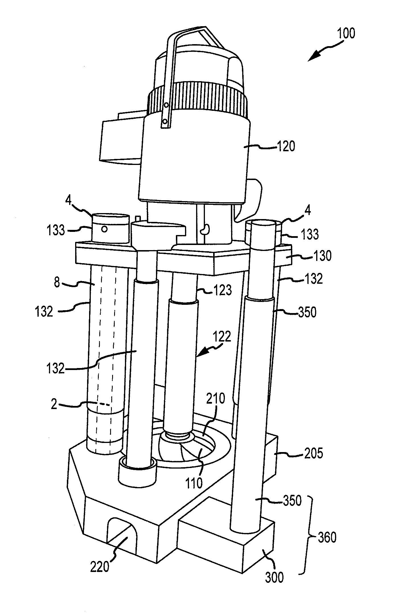
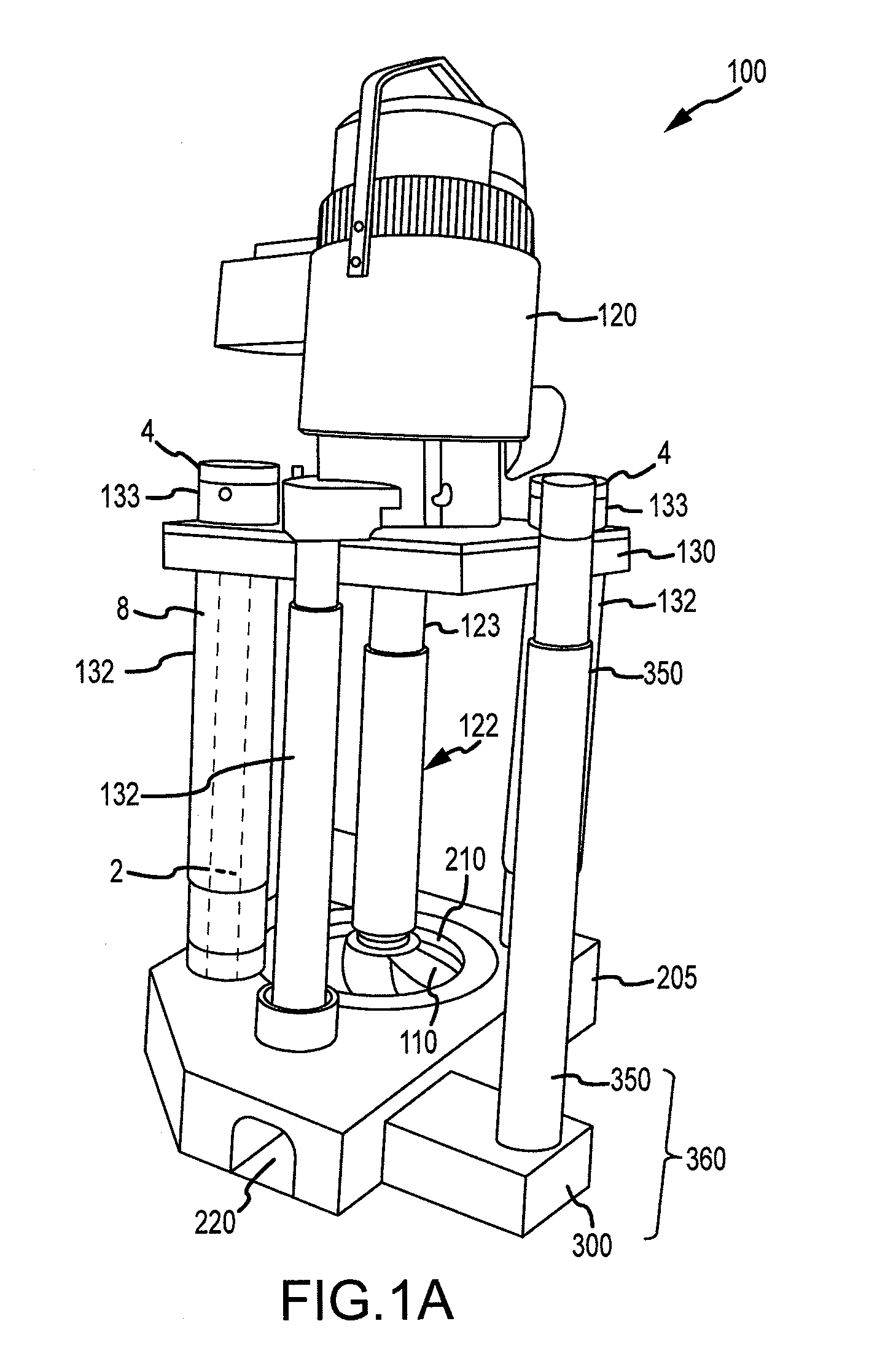
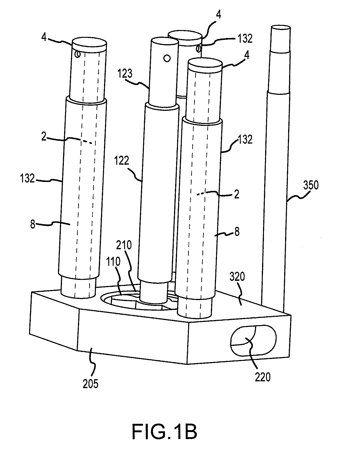
[0025]Reference will now be made in detail to the present exemplary embodiments of the invention, examples of which are illustrated in the accompanying drawings. FIG. 1A depicts a molten metal pump 100 according to the invention. When in operation, pump 100 is typically positioned in a molten metal bath in a pump well, which is typically part of the open well of a reverbatory furnace. Pump 100 includes motor 120, superstructure 130, support posts 132, drive shaft 122, rotor 110, base 205, gas-transfer foot 300 and gas-transfer tube 350.

[0026]The components of pump 100 that are exposed to the molten metal (such as support posts 132, outer core 8, drive shaft 122, rotor 110, base 205, gas-transfer foot 300 and gas-transfer tube 350) are preferably formed of structural refractory materials (previously described), which are resistant to degradation in the molten metal.

[0027]Pump 100 need not be limited to the structure depicted in FIG. 1A, but can be any structure or device for pumping ...


PUM

PropertyMeasurementUnit
axial compressive forceaaaaaaaaaa
tensionaaaaaaaaaa
refractoryaaaaaaaaaa

Abstract

A system for applying tension to a component for use in molten metal processing. Preferably, the component includes an outer core and at least one tension rod positioned partially within the outer core. The component is preferably elongated, such as a support post or an impeller shaft. The tension rod applies compression to the outer cover, which makes the outer cover more resistant to breakage if it strikes, or is stricken by, an object.

Description

BACKGROUND OF THE INVENTION[0001]1. Field of the Invention[0002]The invention relates to a molten metal pump component that has tension applied to it so that the component is more resistant to breakage. More particularly, the invention relates to at least one molten metal pump component comprising a tension rod inside a structural refractory outer core material. This application claims priority to U.S. Provisional Application No. 61 / 232,390 filed on Aug. 7, 2009 to Cooper and entitled “Shaft and Post Tensioning Device.”[0003]2. Description of the Related Art[0004]As used herein, the term “molten metal” means any metal or combination of metals in liquid form, such as aluminum, copper, iron, zinc and alloys thereof. The term “gas” means any gas or combinations of gases, including argon, nitrogen, chlorine, fluorine, Freon, and helium, which can be released into molten metal.[0005]Known pumps for pumping molten metal (also called “molten metal pumps”) include a pump base (also called a...

Claims


Application Information

Patent Timeline
Patent Type & Authority Applications(United States)
IPC IPC(8): F04D29/60F04D29/043F04D29/02B32B9/04B32B15/02B32B18/00
CPCC04B37/025C04B2237/363C04B2237/406C04B2237/62C04B2237/84C04B2237/86Y10T428/2935F04D29/628F04D29/043Y10T428/2938Y10T428/292Y10T428/2958F04D7/065F04D29/02
Inventor COOPER, PAUL V.
Owner MOLTEN METAL EQUIP INNOVIATIONS LLC
Why Eureka
Try Eureka