Elastic wave device

a technology of elastic wave and electrode finger, which is applied in the direction of piezoelectric/electrostrictive/magnetostrictive devices, piezoelectric/electrostriction/magnetostriction machines, etc., can solve the problems of disadvantageously reducing the pitch of the electrode finger of the idt electrode, and reducing the insertion loss. , to achieve the effect of reducing the insertion loss, reducing the s

Active Publication Date: 2011-06-09
MURATA MFG CO LTD
View PDF4 Cites 11 Cited by
  • Summary
  • Abstract
  • Description
  • Claims
  • Application Information

AI Technical Summary

Benefits of technology

[0021]In an elastic wave device according to a preferred embodiment of the present invention, each of the electrode fingers includes the first electrode layer and the second electrode layer, the first electrode layers being located in the grooves, and the second electrode layers being arranged on the first electrode layers and located above the tops of the grooves, and the one-half power of the product of the cube of the mean density (ρa) and the mean stiffness (C44a) of the first electrode layer, i.e., (ρa3×C44a)1 / 2, is preferably set to a value greater than the one-half power of the product of the cube of the mean density (ρb) and the mean stiffness (C44b) of the second electrode layer, i.e., (ρb3×C44b)1 / 2. Thus, it is possible to further reduce the insertion loss. Furthermore, a higher electromechanical coupling coefficient is obtained, thereby achieving a wider band width. Moreover, the acoustic velocity can be increased, so that the pitch of the electrode fingers can be increased. It is thus possible to enhance the resistance to static electricity and the ease of the production.
[0022]Furthermore, in the elastic wave device according to a preferred embodiment of the present invention, the IDT electrodes are covered with the dielectric layer having a temperature coefficient of frequency, and the sign of the temperature coefficient of frequency being opposite to that of the temperature coefficient of frequency of the piezoelectric component, or the sign of the temperature coefficient of frequency of the dielectric layer being the same as that of the temperature coefficient of frequency of the piezoelectric component, and the absolute value of the temperature coefficient of frequency of the dielectric layer being smaller than that of the temperature coefficient of frequency of the piezoelectric component. This makes it possible to reduce the temperature coefficient of frequency.

Problems solved by technology

However, in the case where IDT electrodes with a high density are formed so as to have a large thickness, the acoustic velocity of an elastic wave tends to be low.
Thus, for example, in the case where an elastic wave device using an elastic wave in a high-frequency band, for example, a several hundred megahertz to several gigahertz band, is formed, it is necessary to disadvantageously reduce the pitch of electrode fingers of the IDT electrodes.
A reduction in the pitch of the electrode fingers is liable to cause a reduction in the static electricity resistance of the elastic wave device and the occurrence of a ripple due to an elastic wave in a transverse mode.

Method used


Image

  • Elastic wave device
  • Elastic wave device
  • Elastic wave device

Examples


example 1

CONDITIONS IN EXAMPLE 1

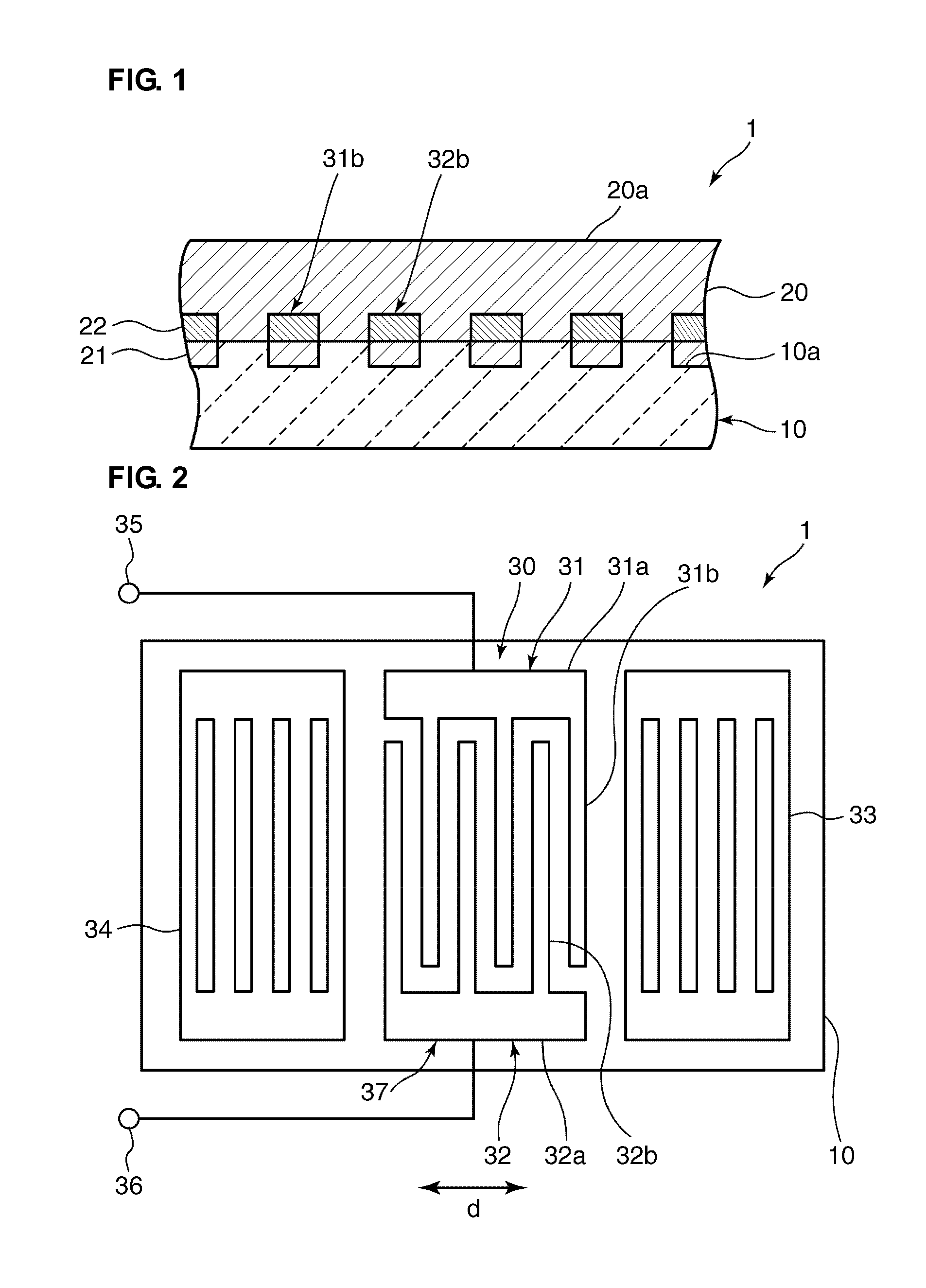
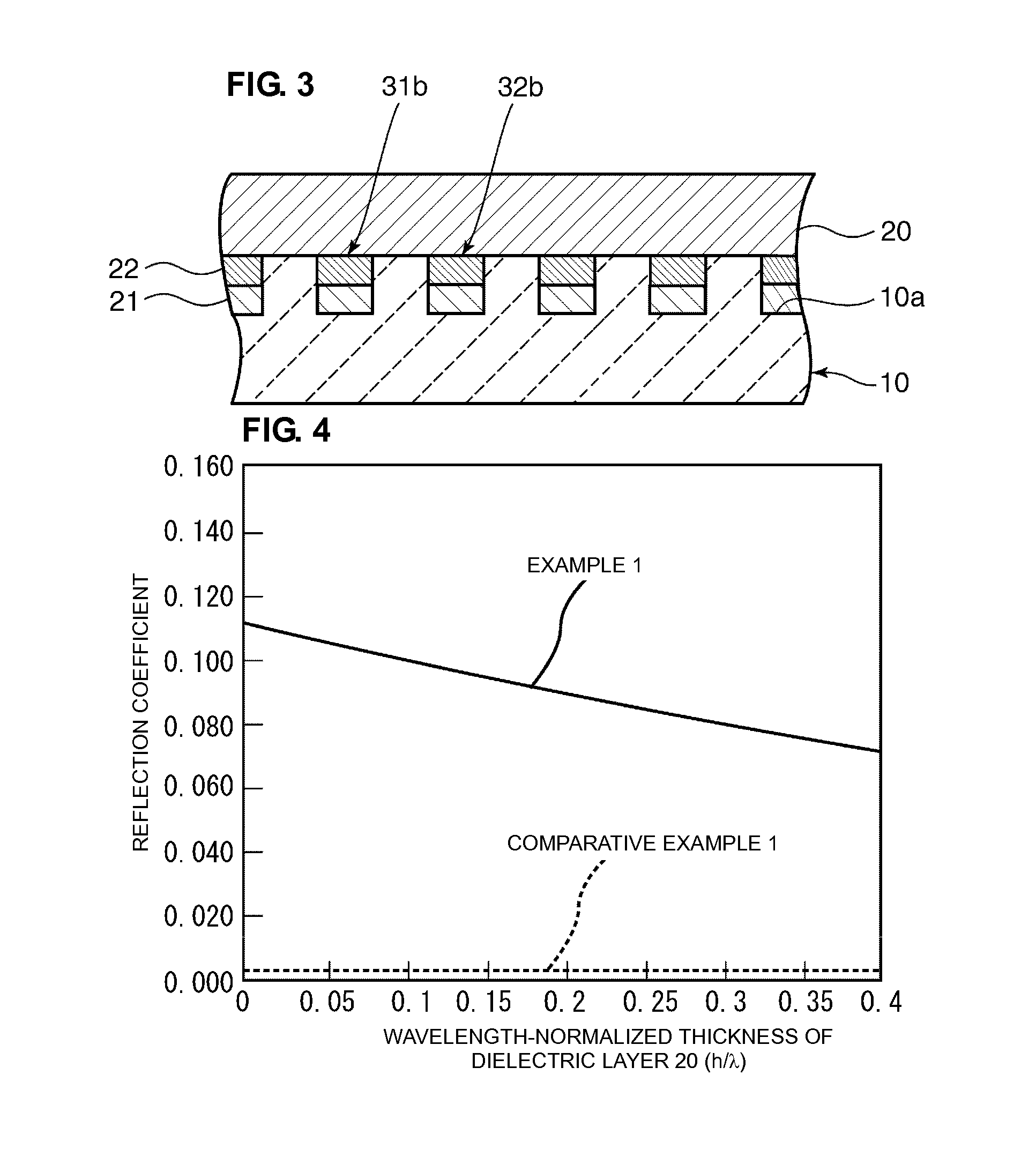
[0079]Piezoelectric component 10: LiTaO3 substrate defined by Euler angles (0°, 128°, 0°)[0080]Thickness (mm) of piezoelectric component 10: 0.38[0081]First electrode layer 21: Pt film[0082]Wavelength-normalized thickness (h / λ) of first electrode layer 21: 0.03[0083]Second electrode layer 22: Al film[0084]Wavelength-normalized thickness (h / λ) of second electrode layer 22: 0.04[0085]Dielectric layer 20: SiO2 layer

[0086]In Comparative Example 1, surface acoustic wave devices as illustrated in FIG. 3 were produced under the same conditions as those in Example 1, except that both the first and second electrode layers 21 and 22 were formed in the grooves 10a of the piezoelectric component 10. The reflection coefficients of the surface acoustic wave devices including the dielectric layers 20 having different thicknesses were measured. The measurement results of the reflection coefficients are indicated by a broken line in a graph shown in FIG. 4.

[0087]In Example 2, ...

example 2

CONDITIONS IN EXAMPLE 2

[0088]Piezoelectric component 10: LiTaO3 substrate defined by Euler angles (0°, 216°, 0°)[0089]Thickness (mm) of piezoelectric component 10: 0.38[0090]First electrode layer 21: Pt film[0091]Wavelength-normalized thickness (h / λ) of first electrode layer 21: 0.03[0092]Second electrode layer 22: Al film[0093]Wavelength-normalized thickness (h / λ) of second electrode layer 22: 0.04[0094]Dielectric layer 20: SiO2 layer

[0095]In Comparative Example 2, surface acoustic wave devices as illustrated in FIG. 3 were produced under the same conditions as those in Example 2, except that both the first and second electrode layers 21 and 22 were formed in the grooves 10a of the piezoelectric component 10. The reflection coefficients of the surface acoustic wave devices including the dielectric layers 20 having different thicknesses were measured. The measurement results of the reflection coefficients are indicated by a broken line in a graph shown in FIG. 6.

[0096]As illustrated...

example 3

CONDITIONS IN EXAMPLE 3

[0101]Piezoelectric component 10: LiTaO3 substrate defined by Euler angles (0°, 128°, 0°)[0102]Thickness (mm) of piezoelectric component 10: 0.38[0103]First electrode layer 21: Pt film[0104]Second electrode layer 22: Al film[0105]Dielectric layer 20: SiO2 layer[0106]Wavelength-normalized thickness (h / λ) of dielectric layer 20: 0.25


PUM


Abstract

An elastic wave device has a low temperature coefficient of frequency (TCF), a low insertion loss, a high electromechanical coupling coefficient (k2), and an increased pitch of the electrode fingers. The elastic wave device includes a piezoelectric component, IDT electrodes, and a dielectric layer arranged to cover the IDT electrodes. The dielectric layer has a temperature coefficient of frequency, the sign of the temperature coefficient of frequency being opposite to that of the temperature coefficient of frequency of the piezoelectric component, or the sign of the temperature coefficient of frequency being the same as that of the temperature coefficient of frequency of the piezoelectric component, and the absolute value of the TCF being smaller than that of the temperature coefficient of frequency of the piezoelectric component. Electrode fingers of the IDT electrodes each include a first electrode layer and a second electrode layer. Each first electrode layer is located in a corresponding one of a plurality of grooves. Each second electrode layer is located above the top of a corresponding one of the grooves. The one-half power of the product of the cube of the mean density (ρa) and the mean stiffness (C44a) of the first electrode layer, i.e., (ρ3×C44)1/2 of the first electrode layer is larger than (ρ3×C44)1/2 of the second electrode layer.

Description

BACKGROUND OF THE INVENTION[0001]1. Field of the Invention[0002]The present invention relates to an elastic wave device for use in, for example, resonators and band pass filters, and more particularly, to an elastic wave device including IDT electrodes covered with an insulating layer.[0003]2. Description of the Related Art[0004]Duplexers (DPXs) and RF filters for use in, for example, mobile communication systems are required to have wide band widths and satisfactory temperature characteristics. With respect to a surface acoustic wave device having a wide band width and satisfactory temperature characteristics, for example, International Publication No. WO 2006 / 011417 A1 discloses a surface acoustic wave device in which Al IDT electrodes embedded in a LiTaO3 substrate are covered with a SiO2 layer having a positive temperature coefficient of frequency (TCF). Like the surface acoustic wave device disclosed in International Publication No. WO 2006 / 011417 A1, embedding the IDT electrod...

Claims


Application Information

Patent Timeline
Patent Type & Authority Applications(United States)
IPC IPC(8): H01L41/047H01L41/08
CPCH03H9/0222H03H9/14541H03H9/02834H03H9/02559
Inventor KIMURA, TETSUYAKADOTA, MICHIO
Owner MURATA MFG CO LTD
Why Eureka
Try Eureka