Power converter

a converter and power technology, applied in the field of power converters, can solve the problems of inrush current flowing from the input capacitor to the clamp capacitor, and the converter cannot regenerate the induced current of an inductive load, and achieve the effects of reducing circuit size and manufacturing cost, convenient configuration, and convenient manufacturing

Active Publication Date: 2011-06-09
DAIKIN IND LTD
View PDF13 Cites 10 Cited by
  • Summary
  • Abstract
  • Description
  • Claims
  • Application Information

AI Technical Summary

Benefits of technology

[0015]According to the first aspect of the power converter of the present invention, in a state of not receiving a signal, the switch part connects one of the input lines with the first DC power supply line through the first diode and connects one of the input lines with the second DC power supply line through the second diode. Accordingly, the converter functions as a rectifier circuit in the state of not receiving a signal. Therefore, when a polyphase AC voltage is applied to the input line in the state in which the switch part does not receive the signal, for example, before the power converter is activated, the clamp capacitor is charged with a DC voltage. In this case, the voltage is applied to the capacitor and the clamp capacitor substantially at the same time, whereby an inrush current is not generated from the capacitor to the clamp capacitor.
[0016]Further, a dedicated charging circuit is not required, whereby a circuit size and a manufacturing cost can be reduced.
[0017]According to the second aspect of the power converter of the present invention, the junction field effect transistor is brought into conduction in a state of not receiving a signal, whereby a junction field effect transistor that is easily configured as a switch part can be used without change. In addition, it is possible to apply a junction field effect transistor that is easily manufactured when configuring it with a wide gap device of SiC, GaN or the like.
[0018]According to the third aspect of the power converter of the present invention, after the clamp capacitor is charged with a voltage, it is possible to made itself function as a direct AC power converter that does not include the power storing means such as a smoothing capacitor between the first and second DC power supply lines. Further, the current returned from the voltage-source inverter can be stored in the clamp capacitor, and the voltage can be kept constant.
[0019]The fourth aspect of the power converter according to the present invention is conducive to achieving the power converter according to the third aspect.
[0020]The object, features, aspects, and advantages of the present invention will be more apparent from the following detailed description in conjunction with the attached drawings.

Problems solved by technology

Therefore, the converter cannot regenerate the induced current of an inductive load that is generated when the inverter is interrupted to the power supply side.
Therefore, if the converter is brought into conduction when the clamp capacitor is discharged, the input capacitor and the clamp capacitor are short-circuited to each other, leading to a possibility that an inrush current may flow from the input capacitor to the clamp capacitor.

Method used


Image

  • Power converter
  • Power converter
  • Power converter

Examples


first embodiment

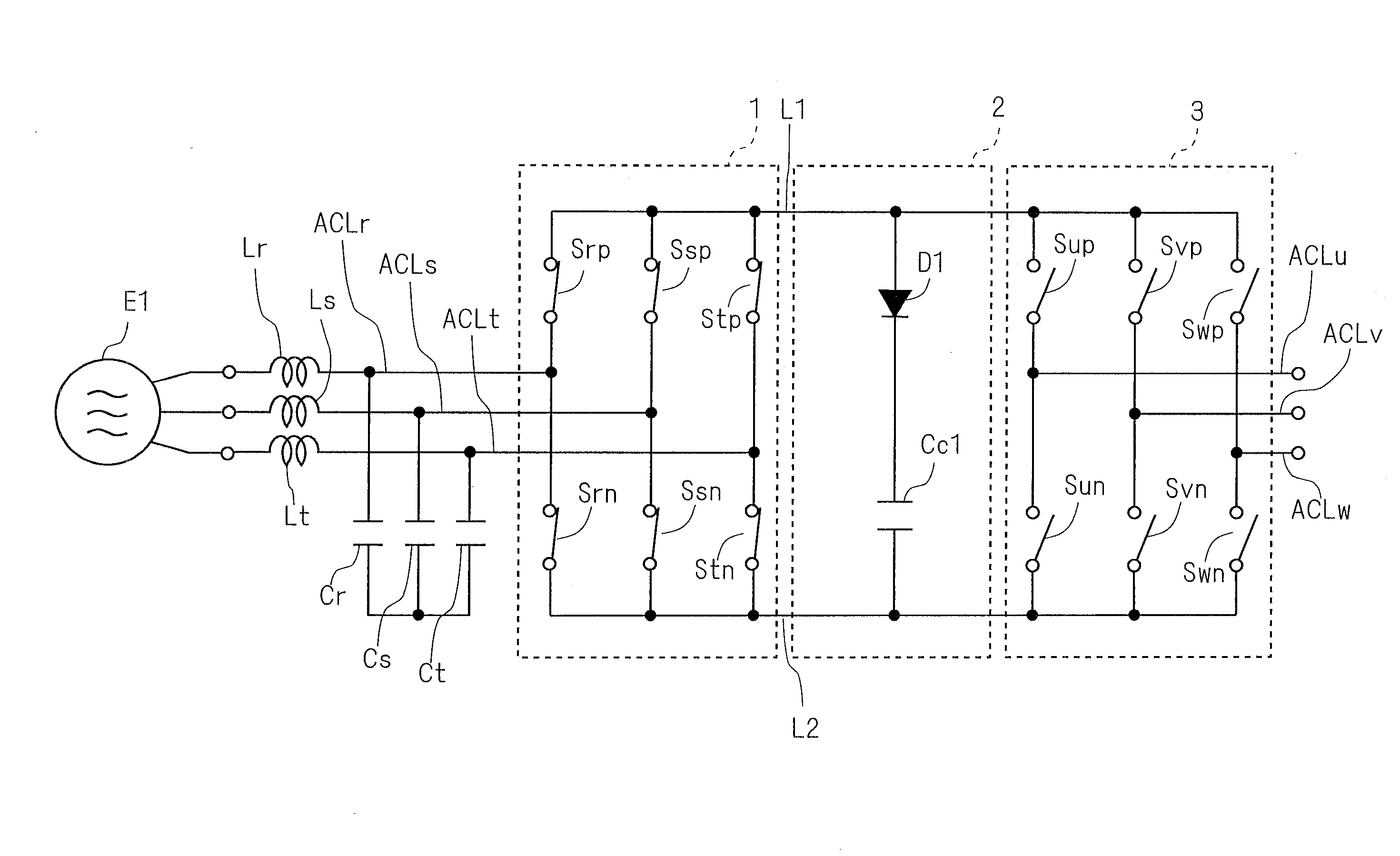
[0029]FIG. 1 shows an example of a conceptual configuration of a direct power converter according to a first embodiment. The direct power converter includes a plurality of input lines ACLr, ACLs and ACLt, reactors Lr, Ls and Lt, capacitors Cr, Cs and Ct, a current-source converter 1, DC power supply lines L1 and L2, a clamp circuit 2, a voltage-source inverter 3, and a plurality of output lines ACLu, ACLv and ACLw.

[0030]The input lines ACLr, ACLs and ACLt are each connected with a power supply E1. The power supply E1 is a polyphase AC power supply and, for example, a three-phase AC power supply. The power supply E1 applies a three-phase AC voltage between ones of the input lines ACLr, ACLs and ACLt.

[0031]The reactors Lr, Ls and Lt are provided on the input lines ACLr, ACLs and ACLt, respectively.

[0032]The capacitors Cr, Cs and Ct are interposed between ones of phases of the input lines ACLr, ACLs and ACLt through, for example, Y-connection. That is, the capacitors Cr and Cs are conn...

second embodiment

[0059]FIG. 6 shows an example of a conceptual configuration of a direct power converter according to a second embodiment. Compared with the direct power converter shown in FIG. 1, a control part 4 is further provided.

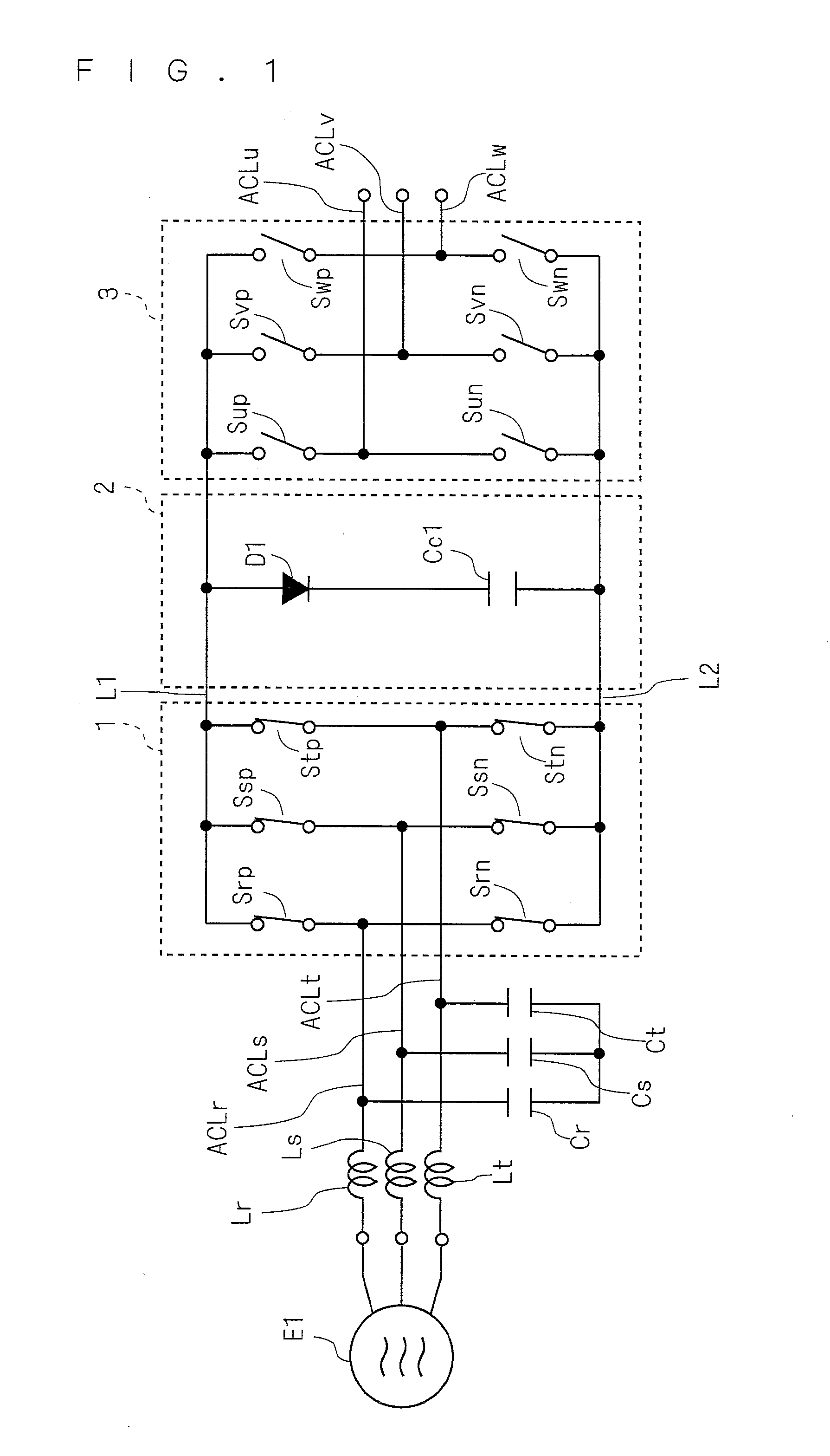
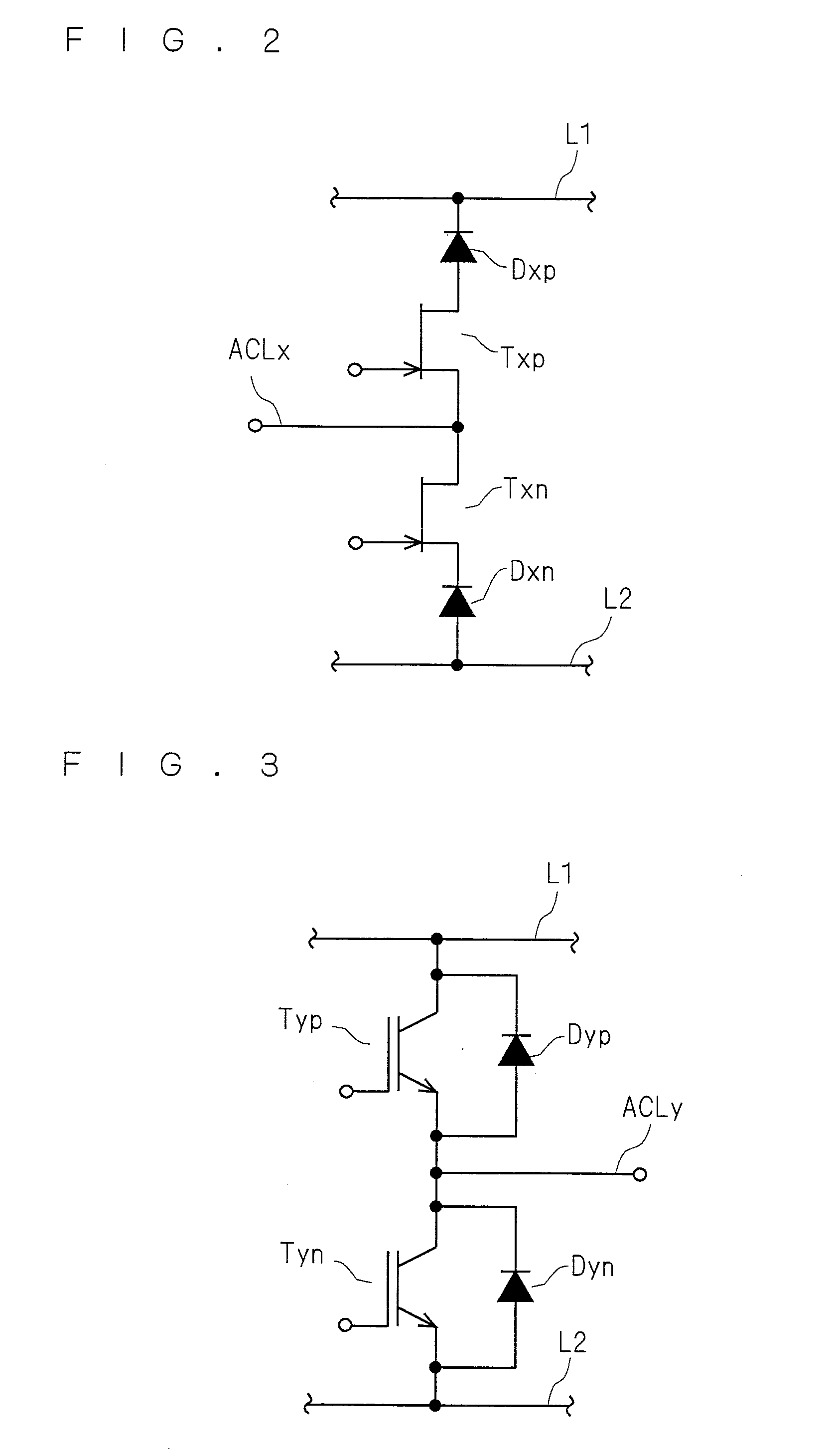
[0060]The control part 4 is connected to both ends of the clamp capacitor Cc1 and uses the voltage across the both ends of the clamp capacitor Cc1 as an operation power supply. The control part 4 supplies signals SSxp and SSxn to the current-source converter 1 (more specifically, transistors Txp and Txn) and supplies signals SSyp and SSyn to the voltage-source inverter 3 (more specifically, transistors Typ and Tyn).

[0061]The transistors Txp, Txn, Typ and Tyn are controlled to be brought into conduction / non-conduction based on the signals SSxp, SSxn, SSyp and SSyn, respectively.

[0062]According to the direct power converter as described above, a rectifier circuit that supplies the operation power supply to the control part 4 can be omitted, and thus a circuit size and a m...

third embodiment

[0065]FIG. 8 shows an example of a conceptual configuration of a direct power converter according to a third embodiment. Note that subsequent stages to the clamp circuit 2 are omitted in FIG. 8. Compared with the direct power converter shown in FIG. 1, resistors R3 and R4 and switches S1 and S2 are further provided.

[0066]The resistors R3 and R4 are provided on at least any two of the input lines ACLr, ACLs and ACLt. For example, the resistors R3 and R4 are provided on the input lines ACLr and ACLt.

[0067]Accordingly, in charging the clamp capacitor Cc1, the current flowing from the power supply E1 to the clamp capacitor Cc1 flows through the resistors R3 and R4, whereby it is possible to reduce the inrush current flowing from the power supply E1 to the clamp capacitor Cc1. Therefore, the inrush current causes no problem even when, for example, an electrolytic capacitor having a large electric capacitance is used as the clamp capacitor Cc1.

[0068]The switches S1 and S2 are, for example...


PUM


Abstract

A plurality of capacitors are interposed between ones of a plurality of input lines. The clamp capacitor is connected between two DC power supply lines. A current-source converter includes a plurality of switch devices, where x represents r, s and t. The switch device selects conduction/non-conduction through a first diode between corresponding one of the input lines and the first DC power supply line and conduction/non-conduction through a second diode between said corresponding one of input lines and the second DC power supply line based on external signals and brings corresponding one of the input lines with the first and second DC power supply lines in a state of not receiving the signals.

Description

TECHNICAL FIELD [0001]The present invention relates to a power converter, and more particularly, to a direct power converter including a clamp capacitor in a DC link.BACKGROUND ART[0002]Lixiang Wei, T. A. Lipo, Ho Chan, “Matrix Converter Topologies with Reduced Number of Switches”, Proc. of PESC 2002, vol. 1, pp. 57-63 (2002) describes a direct power converter with a DC link. In the direct power converter, a converter and an inverter are connected through the DC link to each other.[0003]The converter converts an AC current on an input side to a DC current and outputs it to the DC link. The converter main circuit described therein is incapable of performing conversion opposite thereto, that is, converting the DC current of the DC link to the AC current and outputting it to the input side. Therefore, the converter cannot regenerate the induced current of an inductive load that is generated when the inverter is interrupted to the power supply side.[0004]Accordingly, in Lixiang Wei, T. ...

Claims


Application Information

Patent Timeline
Patent Type & Authority Applications(United States)
IPC IPC(8): H02M5/458
CPCH02M1/32H02M7/219H02M7/2173H02M7/12H02M5/293H02M5/458H02M1/0006
Inventor SAKAKIBARA, KENICHI
Owner DAIKIN IND LTD
Why Eureka
Try Eureka