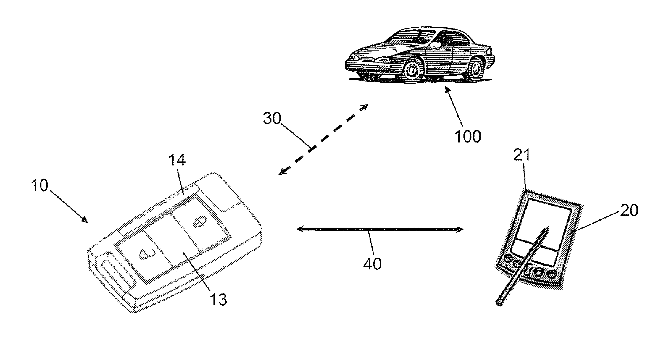
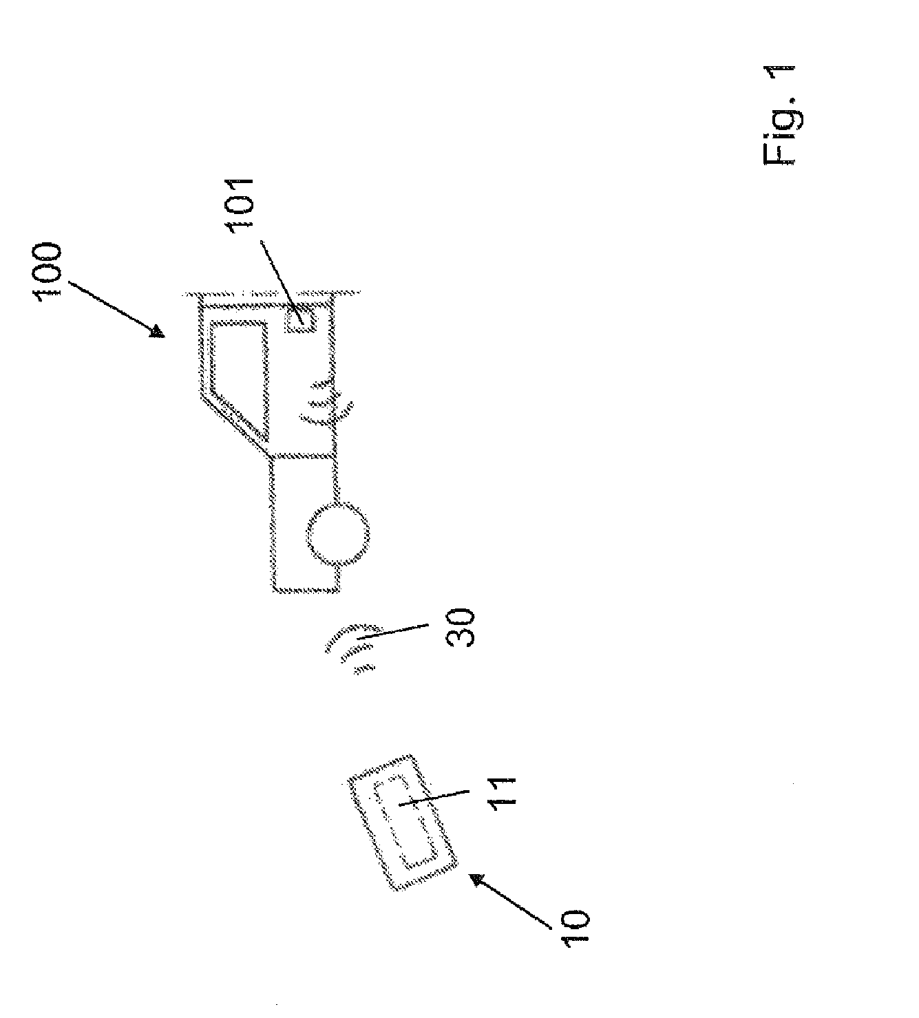
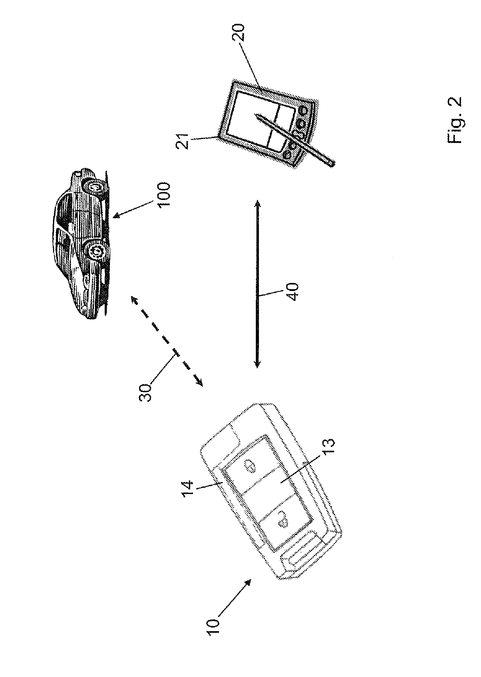
[0008]In the context of an advantageous embodiment of the method according to the invention, it is proposed that the mobile identification
transmitter transmits a query sequence, in which case the display unit receives the query sequence and transmits a response sequence to make the communication connection. A transmission format for the vehicle information can be transmitted in the response sequence. In the context of this alternating question and answer sequence, the requirements to display the vehicle information on the independent display unit are created. The query sequence can lead to execution of the
computer program on the display unit. This
computer program ensures that the vehicle information sent by the mobile ID
transmitter is received by the display unit and displayed accordingly. In addition, different communication interfaces of a display unit can be addressed in parallel by the query sequence. From this number of possibilities, the display unit chooses a corresponding transmission format with the interface setup for it and transmits the corresponding transmission format in the response sequence to the mobile ID transmitter. It is then possible for anyone to adapt the vehicle information to the desired transmission format and transmit to the display unit. This has the
advantage that a user of the method according to the invention can use any display unit available to him, in order to display the vehicle information. The user does not have to rely on preinstalled display units, especially those marketed by the manufacturer of the vehicle.
[0014]The
advantage of this variant is that it can be defined beforehand where the set information is to be displayed. For example a display unit can be chosen depending on the type of vehicle information. On the other hand, it is also possible to mark a number of display units of the same type with an internal code. The identification transmitter according to the invention is then capable of selecting the display unit so marked and transmitting the vehicle information only to this display unit. This type of method according to the invention has proven to be particularly advantageous in the context of management of large fleets of vehicles. The mobile ID transmitters for the different vehicles can be issued at a central vehicle location and later collected again. Depending on different vehicle classes, it is possible to display the vehicle information on pre-established display units. Thus, a simple comparison of individual vehicle classes, like trucks or passenger cars, is possible in the central vehicle location.
[0019]In an advantageous variant of the method according to the invention, the display unit stores and / or processes the vehicle information. The vehicle information can then be evaluated with mathematical methods and / or compared with a reference value. As an alternative, it is also possible to compare the vehicle information with a reference interval. The limits of the reference interval then correspond to stipulated parameters, within which the vehicle information should lie. For example, the engine temperature could be checked whether it surpasses or falls short of a stipulated
limit value. If surpassing of the limits of the reference interval is present, the display unit can display a warning
signal. It is thus easily possible for a user to recognize any deviations and / or errors of the vehicle in a timely fashion and issue a corresponding repair order.
[0024]In order to produce a communication connection between the mobile ID transmitter and the display unit, the former can have a communications device. This
communication device is a transmitter /
receiver unit designed for uni- or
bidirectional transmission of the vehicle information. In particular, the transmitting / receiving unit can be the
transponder. The identification transmitter according to the invention is primarily used for activation of a
security system of the vehicle. This type of mobile identification transmitter has a
transponder that is used to transmit a code to the
security system. As an alternative, the
transponder serves to modulate an electromagnetic wave emitted by the security
system, so that distinct identification of the mobile identification transmitter is possible. By using this transponder as a
communication device, the components can be saved and the method according to the invention can be implemented inexpensively, the electronic unit can store the vehicle information and produce the communication connection to the display unit by transmitting a correspondingly modulated electromagnetic wave by means of the transponder. The latter can have a communication element, in which the communication element is used to make a communication connection to the mobile identification transmitter. The communication element can be a transmitter /
receiver unit equipped similar to the
communication device.
[0026]In an advantageous embodiment, it is proposed that the display unit uses at least one of the following devices: a light-emitting
diode (LED), an organic light-emitting
diode (
OLED), a
liquid crystal display (LCD), a
plasma screen, a
cathode ray tube, a
surface conduction electron emitter display (SED) or a field emission screen (FED). A
liquid crystal display is based on the use of special liquid crystals, which can influence the direction of polarization of light, in order to depict characters, symbols or images. Such LCD screens include a number of segments, in which orientation of liquid crystals can be individually controlled with an electrical field. An SED screen has a similar functionality to a
cathode ray tube. But instead of an individual electronic emitter, an SED screen uses an emitter in each individual subpixel. An
advantage of this type of screen is the rapid reaction time and obtainable contrast.


