
Process gas purification device for a melt reduction system for extracting pig iron

Inactive Publication Date: 2011-06-23
POHANG IRON & STEEL CO LTD +1
View PDF12 Cites 6 Cited by
  • Summary
  • Abstract
  • Description
  • Claims
  • Application Information

AI Technical Summary

Benefits of technology

[0023]The aim of the present invention is to make simple and efficient process gas cleaning possible in the case of a two-stage smelting reduction installation.
[0024]In particular, the droplet separating system of the process gas cleaning installation is to be configured in such a way as to save as much space as possible and in such a way that it can be created with as little expenditure on components as possible. It is a further aim of the present invention to simplify the second wet scrubber system of the second line system carrying the generator gas. Here it is intended to provide a pressure control system that is as efficient as possible, by means of which the outflow of the amount of generator gas or “excess gas” removed from the second line system that is required for controlling the operating pressure of the melter gasifier is minimized.
[0032]In comparison with a process gas cleaning device according to the prior art, it is therefore possible to dispense with one droplet separating device, which results in a considerable saving in terms of space and weight. A droplet separating system according to the invention can be created with relatively little expenditure on components.
[0037]In a further preferred configurational variant of the invention, it is provided that the collector line portion opens out substantially tangentially into the peripheral region of a substantially cylindrically configured droplet separating device. In this way, a swirl is imparted to the blast-furnace gas or generator gas as it flows into the droplet separating device. By means of this swirling effect, the centrifugal force is rendered usable, to achieve better droplet separation.
[0041]By means of a pressure control system according to the invention, with the provision of a bypass valve described, this loss of generator gas, which in the case of a smelting reduction installation according to the prior art is about 1000 m3 / h, can be significantly reduced. This is so since, in the case of relatively small amounts of generator gas brought up to the second wet scrubber system at a given time, the second feed line can be closed by means of the bypass valve, so that fine control of the amount of generator gas then flowing exclusively through the first feed line can take place by means of the pressure control device.
[0042]A further advantage of the pressure control system according to the invention is its flexibility. This is so since, even in the case of a sudden increase in pressure in the melter gasifier, and consequently a large amount of generator gas to be removed by way of the second wet scrubber system, this can be quickly removed in the direction of the export line by the bypass valve or the second feed line being opened. The pressure control is from then on performed by adjusting the control element of the second wet scrubber system or by varying the control gap.

Problems solved by technology

The outflow of a certain amount of generator gas as “excess gas” (usually about 2000 to 10000 m3 / h) is unavoidable, however, in order to reliably control the operating pressure in the melter gasifier.
Such provision of two droplet separating devices is complex and takes up a lot of space in a plant tower provided for the purpose.
This is disadvantageous in particular in the case of retrofitting already existing iron and steel works with COREX / FINEX technology, since only limited space is available.
Such a pressure control system therefore requires the provision of a number of annular-gap scrubbers and is consequently complex to produce and maintain.

Method used


Image

  • Process gas purification device for a melt reduction system for extracting pig iron
  • Process gas purification device for a melt reduction system for extracting pig iron
  • Process gas purification device for a melt reduction system for extracting pig iron

Examples


Embodiment Construction

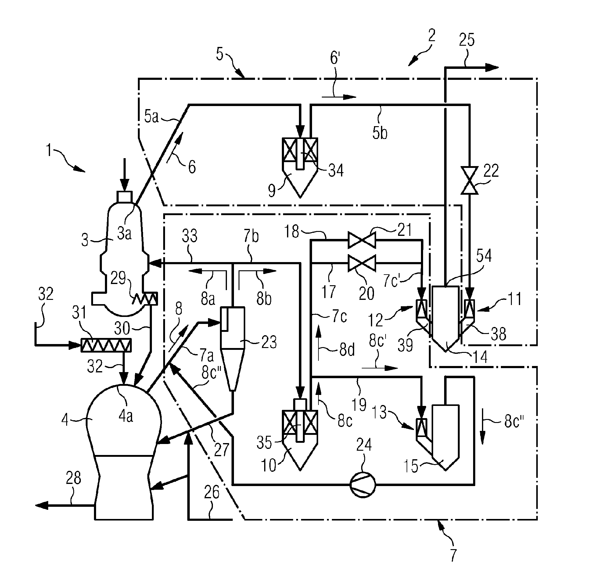
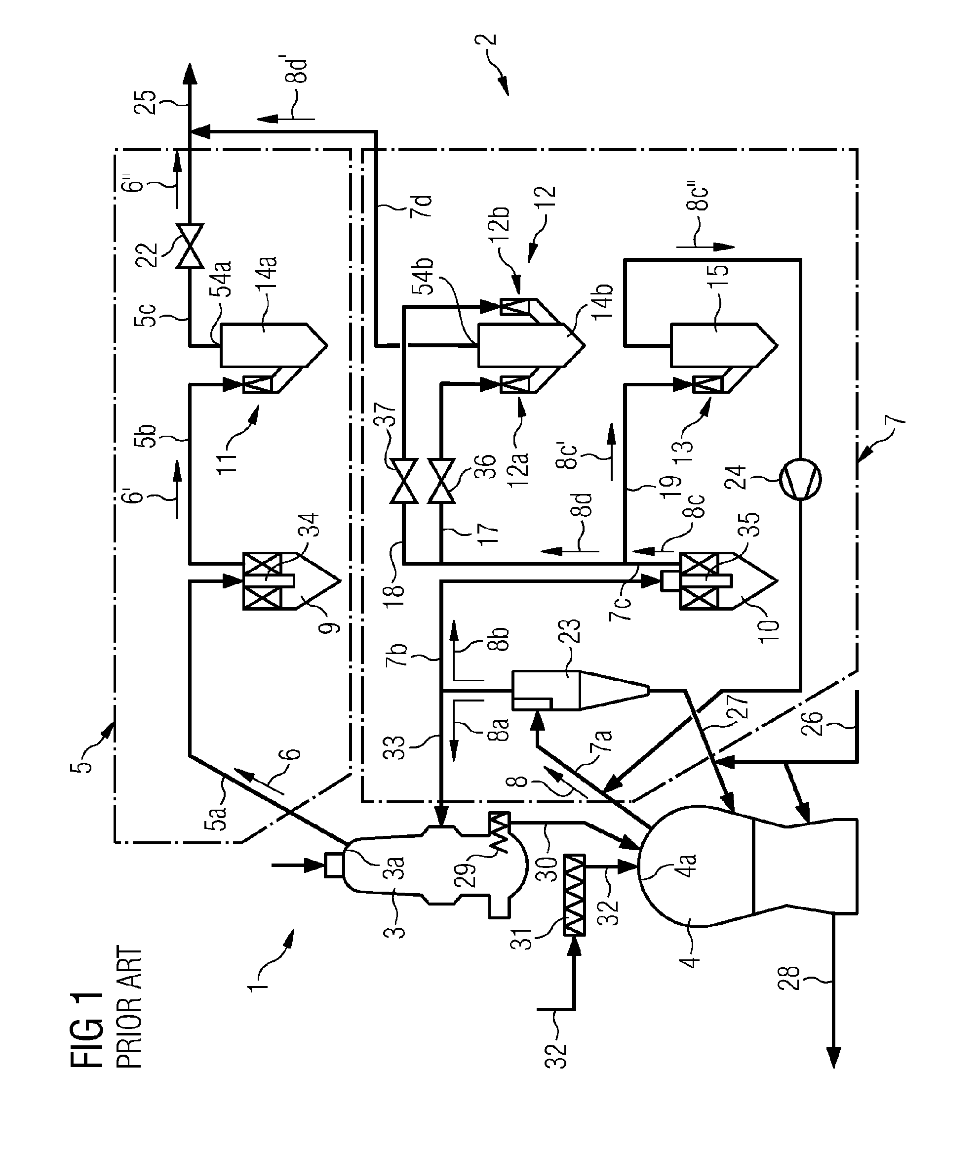
[0062]FIG. 1 shows a two-stage smelting reduction installation 1 according to the prior art, operating on the basis of the COREX process. This smelting reduction installation 1, used for obtaining pig iron or primary steel products, comprises a reduction reactor 3 and a melter gasifier 4 together with a process gas cleaning system 2.

[0063]The reduction reactor 3 is a vessel in the form of a shaft, into which metallurgical charge materials or pieces of lump ore 30 are filled together with any additives.

[0064]The reduction reactor 3 has in its bottom region a discharge opening, through which the metallurgical charge materials 30 can be charged by means of a conveying screw 29 into the melter gasifier 4 arranged underneath the reduction reactor 3. In a hood region 3a, the reduction reactor 3 is connected to a first line system 5, which serves for carrying away blast-furnace gas 6.

[0065]It should be noted that, apart from the COREX process, there are a series of related or further-devel...


PUM

PropertyMeasurementUnit
Timeaaaaaaaaaa
Pressureaaaaaaaaaa
Flow rateaaaaaaaaaa

Abstract

Process gas purification device (2) for a melt reduction system (1) comprising at least one reduction reactor (3) and a melting gasification reactor (4), a first line system (5) for discharging a furnace gas (6) from the reduction reactor (3) and a second line system (7) for discharging a generator gas (8) from the melting gasification reactor (4) wherein both line systems (5,7) lead to a respective wet scrubbing system (11, 12). The furnace gas or generator gas flow can be throttled preferably by way of a control element (41) that varies a control gap (40) and the scrubber or cooling liquid (49) can be collected and drained. The first wet scrubber system (11) of the first line system (5) for routing the furnace gas (6) and the second Venturi scrubber system (12) of the second line system (7) for routing the generator gas (8) both discharge into a common mist elimination device (14).

Description

TECHNICAL FIELD [0001]The invention relates to a process gas cleaning device for a smelting reduction installation for obtaining pig iron, comprising a reduction reactor and a melter gasifier, wherein a first line system for carrying away a blast-furnace gas from the reduction reactor and a second line system for carrying away a generator gas from the melter gasifier are provided, wherein pre-scrubbing devices for pre-cleaning the blast-furnace gas and the generator gas are preferably arranged within the first and second line systems and wherein the first and second line systems respectively lead to a wet scrubber system, which is preferably formed as an annular-gap scrubber system and in which the blast-furnace gas or the generator gas can be subjected to scrubbing or cooling liquid and the throughflow of the blast-furnace gas or of the generator gas can be throttled by means of one or more control elements varying a control gap and wherein the scrubbing or cooling liquid introduce...

Claims


Application Information

Patent Timeline
IPC IPC(8): B01D53/14B01D53/34
CPCB01D47/06B01D47/10C21B13/002F27D17/008C21B13/14F27B1/18C21B13/0073C21B2100/44C21B2100/64Y02P10/134
Inventor KANG, SIN-MYOUNGSCHENK, JOHANNES LEOPOLDSCHMIDT, MARTINWIEDER, KURTWURM, JOHANN
Owner POHANG IRON & STEEL CO LTD
Learn More