Polycrystalline sic electrical devices and methods for fabricating the same

a technology of polycrystalline sic and electrical devices, which is applied in the field of new electrical devices, can solve the problems of reducing the market potential of gas igniters, and reducing the use of standing pilot lights

Active Publication Date: 2011-06-23
SURFACEIGNITER
View PDF6 Cites 11 Cited by
  • Summary
  • Abstract
  • Description
  • Claims
  • Application Information

AI Technical Summary

Benefits of technology

[0018]A method is provided for forming polymer-ceramic composite igniter shapes that are pyrolized in supporting fixtures at temperatures as low as 650° C. in nitrogen or other inert gas atmospheres. This pyrolizing step converts the impregnated resin content to 70% to 80% silicon carbide by weight enabling a permanent SiC bonding phase at temperatures as low as 650° C., thereby creating a self supporting structure within an operational temperature ranges of 650° C. and approximately 2000° C., allowing substantially self-supporting / support-free firing orientations during downstream recrystallization and resultant production efficiencies.
[0019]The resulting material is a ceramic-bonded particulate ceramic composite that will later be recrystallized to attain desired electrical and mechanical properties. The balance of the resin content (30% to 20% by weight) is volatilized as hydrogen, hydrocarbon and pyrophoric silane waste gases. The supporting fixtures serve to limit dimensional distortion of the individual igniter shapes during the conversion reaction.
[0022]In summary, this invention provides an improved electrical SiC method and product, where the example product (the silicon carbide igniter above described) is of superior quality in terms of material properties (reflected in for example material density, consistency, electrical stability, mechanical strength, mechanical toughness and durability), improved operational life (in terms of durational time to failure), and other benefits.
[0023]The present invention will also result in substantial improvements to correspondingly processing time and manufacturing costs, firing energy, and product field replacement and quality control costs.
[0025]The present invention relates to an improved method for production of silicon carbide igniter bodies exhibiting a permanent SiC bonding phase at temperatures as low as 650° C. resulting in an uncommon degree of structural strength for a ceramic bisque product.

Problems solved by technology

These standards largely led to the demise of the standing pilot light for many appliance types and greatly increased the market potential for gas igniters.
A recognition that the metal alloys used for spark electrodes erode and become pitted with use, reducing their effectiveness.
Yet despite the recognition provided to SiC hot surface igniters, certain detriments remain.
Unfortunately, despite the above-recognition, in existing SiC igniter product examples, a typical 84% to 86% SiC density corresponds to a relatively high 16% to 14% interspermosing (meaning operable or flow-able interstecies between particles) porosity which is easily permeated by air and moisture, much like an open cell foam structure.
Such detrimental porosity leads directly to excessive material oxidation at operational temperatures, mechanical stress, electrical property “aging” and resultant premature failure of the product.
These products (these grouped together and referred to as “nitride” igniters herein) are superior in mechanical strength but cannot match the service longevity and functional robustness of conventional SiC igniters.
Specifically, nitride ceramics are limited in their detrimental high temperature capability in oxidizing environments as compared to silicon carbide (SiC) igniters.

Method used


Image

  • Polycrystalline sic electrical devices and methods for fabricating the same
  • Polycrystalline sic electrical devices and methods for fabricating the same
  • Polycrystalline sic electrical devices and methods for fabricating the same

Examples


Embodiment Construction

[0030]Reference will now be made in detail to the discussion supported by the accompanying illustrations. These drawings are in simplified form and are not to precise scale but are operative for assisting an understanding of the method herein. For purposes of convenience and clarity only, directional terms, such as top, bottom, up, down, over, above, and below may be used with respect to the drawings. These and similar directional terms should not be construed to limit the scope of the invention in any manner.

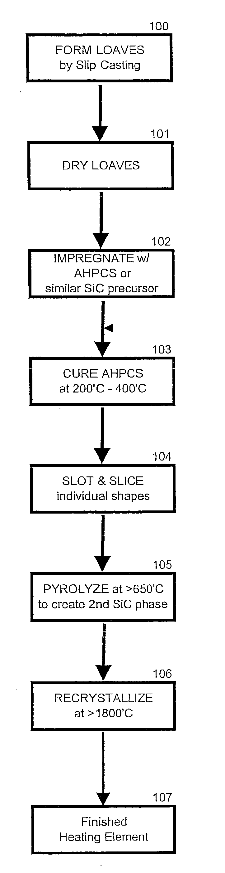
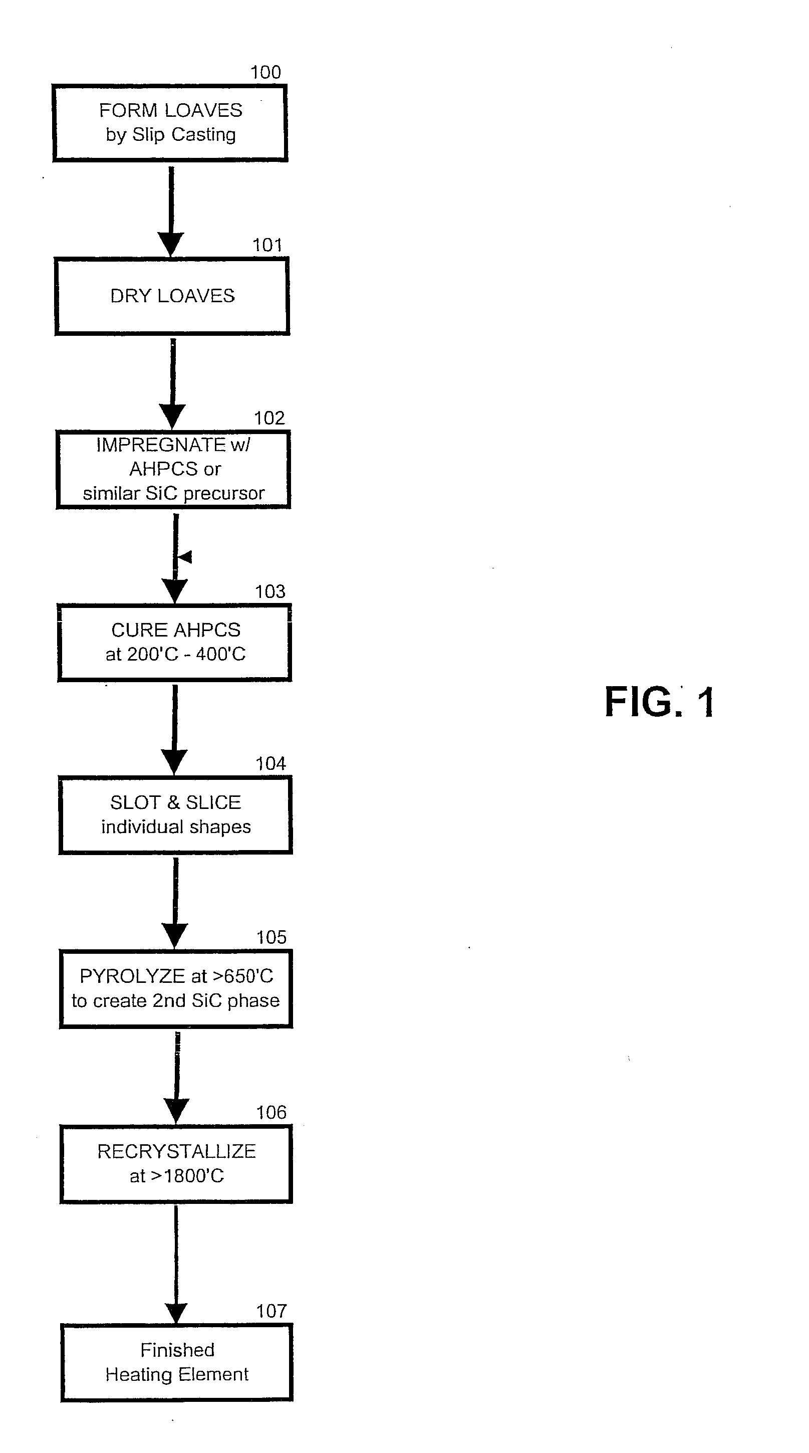
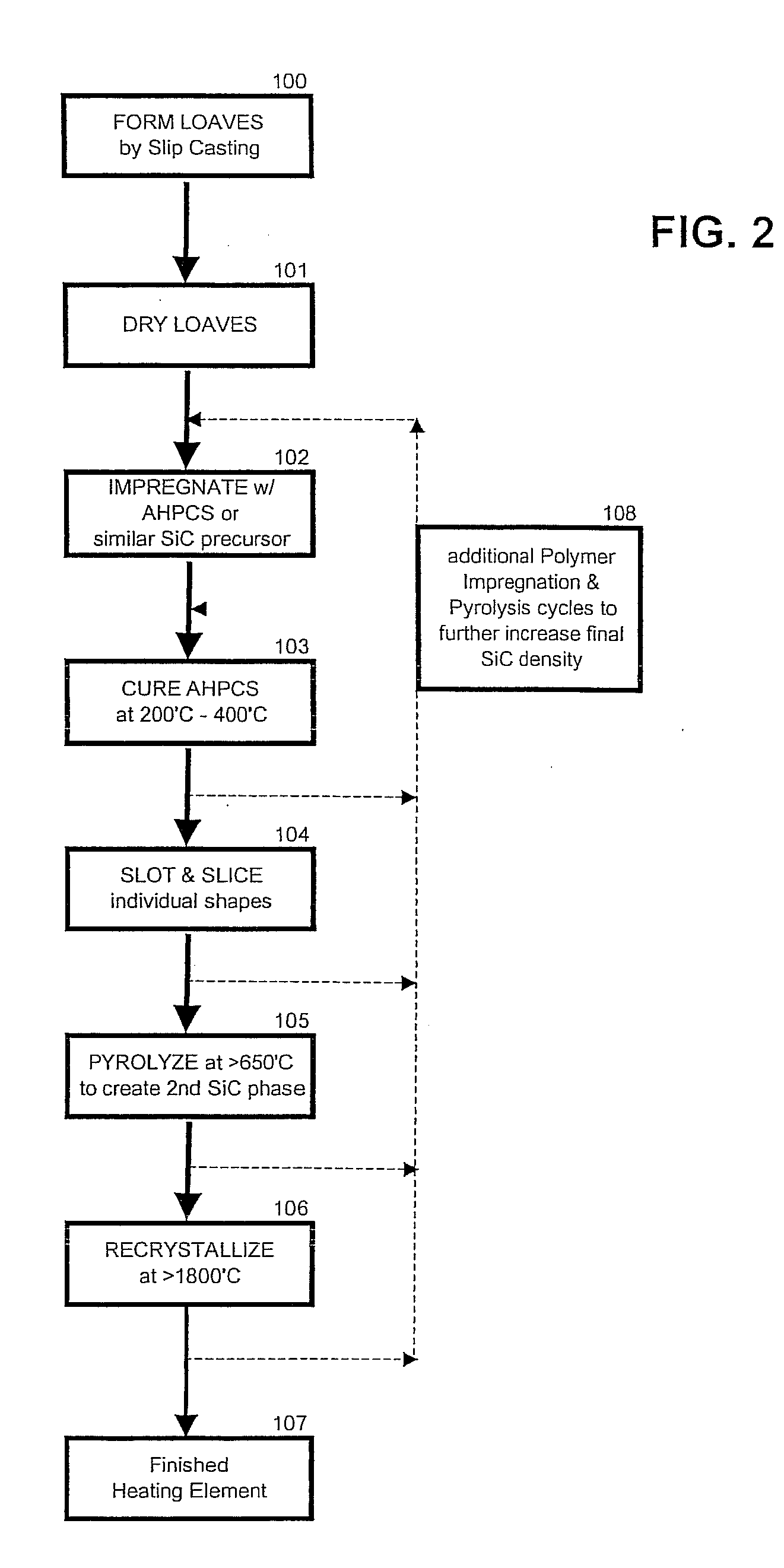
[0031]This invention relates to novel electrical devices, including the hot surface igniters discussed above, fabricated from polycrystalline silicon carbide (SiC) and methods for forming the same. However, it shall be recognized that as used herein a hot surface igniter is merely a representative example wherein the heating element portion is composed of silicon carbide, that the present invention is not limited thereto and has broader applications throughout the industry.

[003...


PUM

PropertyMeasurementUnit
temperatureaaaaaaaaaa

Abstract

The present invention relates to a novel electrical devices fabricated from polycrystalline silicon carbide (SiC) and methods for forming the same. The present invention provides a method for fabricating polycrystalline silicon carbide (SiC) products infiltrated with SiC-containing preceramic precursor resins to substantially mask the deleterious effects of trace contaminants, typically nitrogen and aluminum, while reducing operative porosity and enhancing manufacturing ease.

Description

CROSS REFERENCE TO RELATED APPLICATIONS[0001]This application claims priority from U.S. Ser. No. 12 / 092,801 filed May 6, 2008, which in turn claims priority to PCT App. Ser. No. PCT / US06 / 60634 filed Nov. 7, 2007, which in turn claims priority from U.S. Prov. App. No. 60 / 734,127 filed Nov. 7, 2005, the entire contents of each of which are herein incorporated by reference.BACKGROUND OF THE INVENTION[0002]1. Field of the Invention[0003]The present invention relates to novel electrical devices fabricated from polycrystalline silicon carbide (SiC) and methods for forming the same. More specifically, the present invention provides a method for fabricating polycrystalline silicon carbide (SiC) products infiltrated with SiC-containing preceramic precursor resins to substantially mask the deleterious effects of trace contaminants, typically nitrogen and aluminum, while reducing operative porosity and enhancing manufacturing ease.[0004]2. Description of the Related Art[0005]Prior to the adven...

Claims


Application Information

Patent Timeline
Patent Type & Authority Applications(United States)
IPC IPC(8): C04B35/565
CPCC04B35/571C04B35/6269C04B2235/3217C04B2235/3826C04B2235/402C04B2235/612F23N2027/42C04B2235/656C04B2235/72C04B2235/722C04B2235/762C04B2235/767C04B2235/77C04B2235/616F23N2227/42
Inventor COLOPY, CURTIS M.
Owner SURFACEIGNITER
Why Eureka
Try Eureka